Sony HVR1500A Product Manual (HVE-1500A Operating Manuals) - Page 81
VIDEO CONTROL [Video]: Settings related to video, OUT REF SEL [> Out Ref]
 |
View all Sony HVR1500A manuals
Add to My Manuals
Save this manual to your list of manuals |
Page 81 highlights
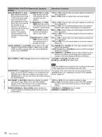
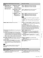
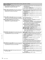
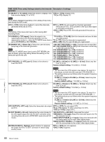
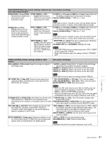
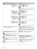
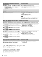
TAPE PROTECTION [Tape protct]: Settings related to tape Description of settings and video head protection FROM STOP [> From STOP]: Set the time to switch from stop mode to tape protection mode. STOP TIMER [>> STP timer]: Set the time to switch from stop mode to tape protection mode. 0.5 SEC [>>> 0.5 sec] to 5 MIN [>>> 5 min]: Select time from 12 settings ranging from 0.5 second to 5 minutes. Factory default setting: *1 MIN [>>> 1 min] Note If the value is set to 1 minute or more, the unit enters internal protection mode in 1 minute, which makes start up slower. FROM STILL [> From STILL TIMER [>> STL STILL]: Set the time to timer]: Set the time to switch from still search switch from still search mode to tape protection mode to tape protection mode. Also select the type mode. of tape protection mode. 0.5 SEC [>>> 0.5 sec] to 5 MIN [>>> 5 min]: Select time from 12 settings ranging from 0.5 second to 5 minutes. Factory default setting: *1 MIN [>>> 1 min] Note If the value is set to 1 minute or more, the unit enters internal protection mode in 1 minute, which makes start up slower. NEXT MODE [>> Next mode]: Select the type of tape protection mode to follow still search mode when the time set with the STILL TIMER menu item elapses. *STEP FWD [>>> Step]: The tape is advanced at 1/30 times normal speed for about 2 seconds. STANDBY OFF [>>> STANDBY]: Standby off mode Notes • The STEP FWD setting is enabled only when "STILL TIMER" is set to less than 1 minute. • When HDV format is used, the setting is fixed to STANDBY OFF. VIDEO CONTROL [Video]: Settings related to video control STILL MODE [> STILL mod]: Select the image to output in still image mode. Description of settings *AUTO [>> Auto]: Output field 1 or field 2 as the still image, according to the position the tape is stopped. FRAME [>> Frame]: Output a full frame as the still image. FIELD1 [>> Field 1]: Output only field 1 as the still image. FIELD2 [>> Field 2]: Output only field 2 as the still image. INT VIDEO SG [> Video SG]: Select the test signal to be used when SG is selected as the video input with the INPUT SELECT buttons. Note When HDV format is used, the setting is fixed to FIELD2. *75% COLOR BARS [>> 75% bar]: 75% color bar signal 100% COLOR BARS [>> 100% bar]: 100% color bar signal BLACK BURST [>> BB]: Black burst signal Notes • When the HD video input is set to SG, the 100% color bar signal is displayed regardless of whether 75% COLOR BARS or 100% COLOR BARS is selected. • With the SD video input set to SG, the 100% color bar signal is displayed only when the system frequency is set to 50i. STD/NON-STD [> STD/N-STD]: Set whether to use the unit in *FORCED STD [>> STD]: The STD mode is always used STD (standard) or NON-STD (non-standard) mode (forced STD mode). depending on the condition of composite video or S-video FORCED NON-STD [>> NON-STD]: Use this setting when the input. input video signal is unstable (forced NON-STD mode). OUT REF SEL [> Out Ref]: When signals are input to both the VIDEO IN connector and the REF. VIDEO IN connector, select which signal to use as the reference signal for playback in EDIT mode. *REF VIDEO [>> REF]: Use the signal input to a REF. VIDEO IN (SD/HD) connector as the reference video signal. The input video signal to be edited is required to be in synchronization with the reference video signal. INPUT VIDEO [>> INPUT]: Use the input video signal as the reference signal. SETUP REMOVE [> Setup rmv]: Determine whether or not to remove black setup (7.5 IRE) from input analog video signals when converting them into digital signals. *OFF [>> OFF]: Do not remove black setup. ON (REMOVE) [>> ON]: Remove black setup. Note Displayed only when the system frequency is set to 60i. Chapter 7 Menus 81 Menu Contents
-
 1
1 -
2
-
3
-
4
-
5
-
6
-
7
-
8
-
9
-
10
-
11
-
12
-
13
-
14
-
15
-
16
-
17
-
18
-
19
-
20
-
21
-
22
-
23
-
24
-
25
-
26
-
27
-
28
-
29
-
30
-
31
-
32
-
33
-
34
-
35
-
36
-
37
-
38
-
39
-
40
-
41
-
42
-
43
-
44
-
45
-
46
-
47
-
48
-
49
-
50
-
51
-
52
-
53
-
54
-
55
-
56
-
57
-
58
-
59
-
60
-
61
-
62
-
63
-
64
-
65
-
66
-
67
-
68
-
69
-
70
-
71
-
72
-
73
-
74
-
75
-
 76
76 -
 77
77 -
 78
78 -
 79
79 -
 80
80 -
 81
81 -
 82
82 -
 83
83 -
 84
84 -
 85
85 -
 86
86 -
87
-
88
-
89
-
90
-
91
-
92
-
93
-
94
-
95
-
96
-
97
-
98
-
99
-
100
-
101
-
102
-
103
-
104
-
105
-
106
-
107
-
108
-
109
-
110
-
111
 |
 |
