Sony VPL-FX30 Operating Instructions - Page 35
Attach Part A and Part B for the lens
 |
View all Sony VPL-FX30 manuals
Add to My Manuals
Save this manual to your list of manuals |
Page 35 highlights
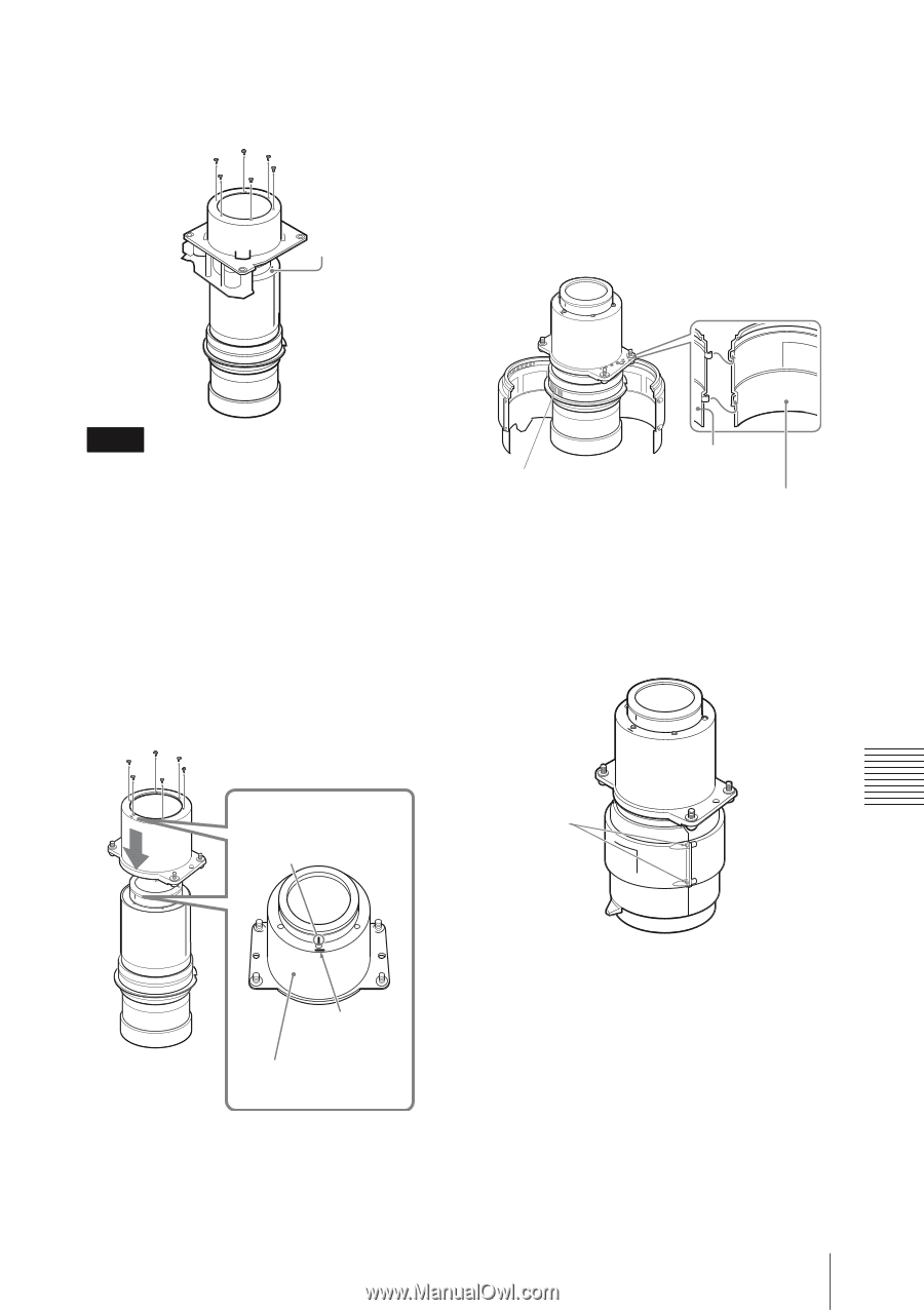
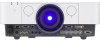
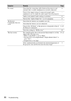
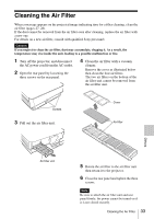
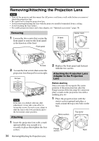
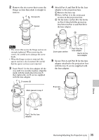
2 Remove the six screws that secure the flange section then slide it straight to remove. Screws (6) Spacer 4 Attach Part A and Part B for the lens adapter to the projection lens. 1 Remove the lens cap. 2 First, fit Part A to the zoom gear section on the projection lens. 3 Fit the holes on Part B to the hooks on Part A then hold the projection lens between Part A and Part B for the lens adapter. 3 2 Notes • The screws that secure the flange section are strongly tightened. When removing the screws, be careful not to damage the screw heads. • When the flange section is removed, the spacer section is also loosened. Be careful that the spacer section is not removed. 3 Insert Part C for the lens adapter all the way until it is securely in place, align the mark with the mark placed in step 1, then tighten the six D screws supplied with the lens adapter. D screws (6) Mark placed in step 1 Zoom gear section Part A for the lens adapter Part B for the lens adapter 5 Secure Part A and Part B for the lens adapter attached to the projection lens with the two E screws supplied with the lens adapter. E screws (2) Others Mark Part C for the lens adapter Removing/Attaching the Projection Lens 35
-
 1
1 -
2
-
3
-
4
-
5
-
6
-
7
-
8
-
9
-
10
-
11
-
12
-
13
-
14
-
15
-
16
-
17
-
18
-
19
-
20
-
21
-
22
-
23
-
24
-
25
-
26
-
27
-
28
-
29
-
 30
30 -
 31
31 -
 32
32 -
 33
33 -
 34
34 -
 35
35 -
 36
36 -
 37
37 -
 38
38 -
 39
39 -
 40
40 -
41
-
42
-
43
-
44
-
45
-
46
-
47
-
48
-
49
 |
 |