Sony VPL-FX30 Operating Instructions - Page 4
Connector Panel, S VIDEO S VIDEO - image
 |
View all Sony VPL-FX30 manuals
Add to My Manuals
Save this manual to your list of manuals |
Page 4 highlights
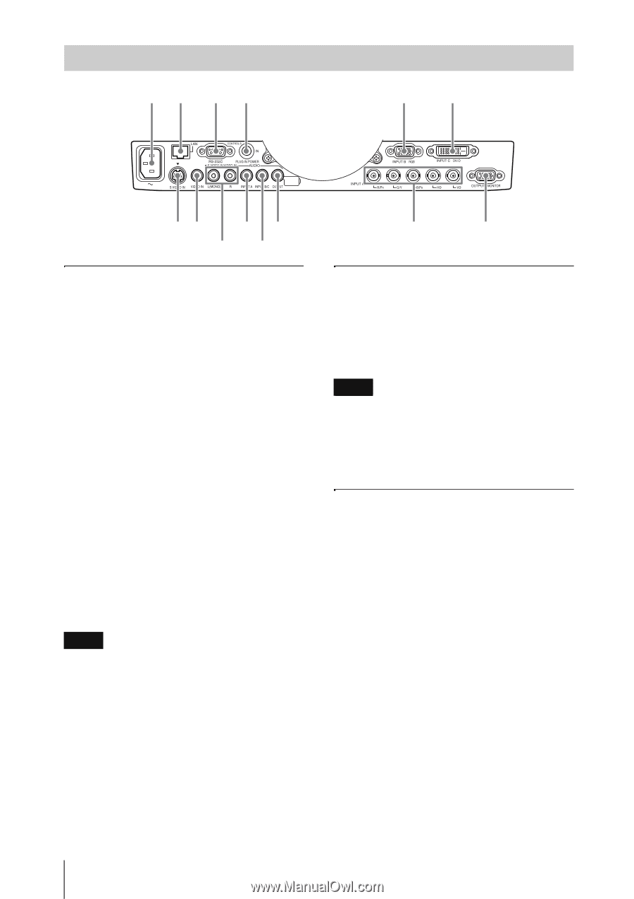
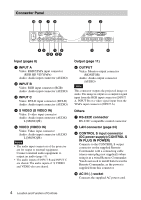
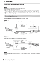
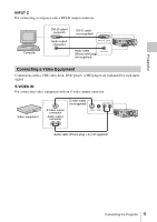
Connector Panel q; 8 7 9 23 45 1 6 45 23 Input (pages 8) a INPUT A Video: RGB/YPBPR input connector (RGB HD VD/YPBPR) Audio: Audio input connector (AUDIO) b INPUT B Video: RGB input connector (RGB) Audio: Audio input connector (AUDIO) c INPUT C Video: DVI-D input connector (DVI-D) Audio: Audio input connector (AUDIO) d S VIDEO (S VIDEO IN) Video: S video input connector Audio: Audio input connector (AUDIO L [MONO]/R) e VIDEO (VIDEO IN) Video: Video input connector Audio: Audio input connector (AUDIO L [MONO]/R) Notes • The audio input connectors of the projector are for output to external equipment. Connect external audio equipment to output an audio (page 11). • The audio inputs of INPUT B and INPUT C are shared. The audio inputs of S VIDEO and VIDEO also are shared. 1 6 Output (page 11) f OUTPUT Video: Monitor output connector (MONITOR) Audio: Audio output connector (AUDIO) Note This connector outputs the projected image or audio. The image is output as a computer signal input from the RGB input connector (INPUT A, INPUT B) or a video signal input from the YPBPR input connector (INPUT A). Others g RS-232C connector RS-232C compatible control connector h LAN connector (page 24) i CONTROL S input connector (DC power supply) (CONTROL S IN PLUG IN POWER) Connects to the CONTROL S output connector on the supplied Remote Commander with a connecting cable (stereo mini plug (not supplied)) when using it as a wired Remote Commander. You do not need to install batteries in the Remote Commander, as the power is supplied from this connector. j AC IN (∼) socket Connects the supplied AC power cord. 4 Location and Function of Controls
-
 1
1 -
 2
2 -
 3
3 -
 4
4 -
 5
5 -
 6
6 -
 7
7 -
 8
8 -
 9
9 -
 10
10 -
11
-
12
-
13
-
14
-
15
-
16
-
17
-
18
-
19
-
20
-
21
-
22
-
23
-
24
-
25
-
26
-
27
-
28
-
29
-
30
-
31
-
32
-
33
-
34
-
35
-
36
-
37
-
38
-
39
-
40
-
41
-
42
-
43
-
44
-
45
-
46
-
47
-
48
-
49
 |
 |