Sony VPL PX31 Operating Instructions - Page 12
Connector panel
 |
UPC - 027242578814
View all Sony VPL PX31 manuals
Add to My Manuals
Save this manual to your list of manuals |
Page 12 highlights
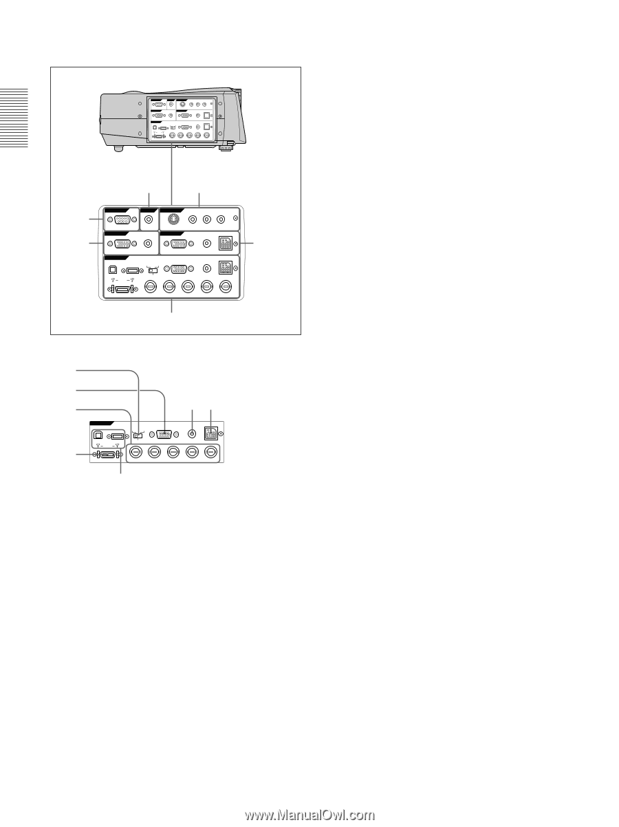
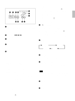
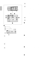
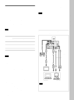
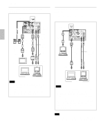
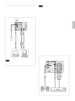
Location and Function of Controls Connector panel Right side REMOTE RS-232C OUTPUT CONTROL S VIDEO IN IN PLUG IN POWER S VIDEO VIDEO INPUT B L R (MONO) AUDIO MONITOR INPUT A USB AUDIO DIGITAL RGB RGB 5BNC RGB RGB AUDIO MOUUSE AUDIO MOUUSE DIGITAL RGB R/R-Y/PR G/Y B/B-Y/PB SYNC/HD VD 4 3 5 6 REMOTE RS-232C OUTPUT CONTROL S VIDEO IN IN PLUG IN POWER S VIDEO VIDEO INPUT B L R (MONO) AUDIO MONITOR INPUT A USB AUDIO DIGITAL RGB RGB 5BNC RGB RGB AUDIO MOUSE AUDIO MOUSE DIGITAL RGB R/R-Y/PR G/Y B/B-Y/PB SYNC/HD VD 1 2 1 INPUT A connectors 1 2 3 4 76 INPUT A USB DIGITAL RGB RGB 5BNC RGB AUDIO MOUSE DIGITAL RGB R/R-Y/PR G/Y B/B-Y/PB SYNC/HD VD 5 1DIGITAL RGB/5BNC/RGB switch: Selects DIGITAL RGB, 5BNC or RGB on INPUT A connectors. Select the appropriate position depending on the input signal. DIGITAL RGB: Signal input from DIGITAL RGB connector. 5BNC: Signal input from the 5BNC connector. RGB: Signal input from the RGB connector. 2RGB input connector (HD D-sub 15-pin, female): Connects to the monitor output on a computer using the supplied cable. This connector only accepts signals from a computer. 35BNC input connectors (R/R-Y/PR, G/Y, B/BY/PB, SYNC/HD, VD connectors) (BNC type): Connect to a high-resolution computer or VCR where signals are transmitted long distances; for example, when the projector has been hung from the ceiling. According to the connected equipment, computer, component (R-Y/Y/B-Y), HDTV or DTV (DTV GBR, DTV YPBPR) signal is selected. 12 (GB) 4DIGITAL RGB input connector (DFP 20-pin, TMDS): Connects to a digital RGB output connector on external equipment. 5USB connector: Connects your computer or USB equipment. A plug: (Right, for downstream, 4-pin): Connects to USB equipment. B plug: (Left, for upstream, 4-pin): Connects to a computer. If you connect the projector and a computer, the projector automatically assumes that a USB mouse is connected; this allows you to control the mouse from the Remote Commander. The application software supplied with the projector allows you to control the projector from your computer. 6MOUSE (13-pin) connector: Connects to the mouse port on a computer to control the mouse function using the supplied mouse cable. 7AUDIO (stereo mini-jack) jack: Connects to the audio output on a computer. 2 INPUT B connectors Connect to external equipment such as a computer. You can control the mouse signal with the Remote Commander. RGB input (HD D-sub 15-pin, female): Connects to the monitor output on a computer using the supplied cable. This connector only accepts signals from a computer. AUDIO (stereo mini-jack): Connects to the audio output on a computer. MOUSE (13-pin): Connects to the mouse port on a computer to control the mouse function using the supplied mouse cable. 3 VIDEO IN jacks Connect to external video equipment such as a VCR. S VIDEO (mini DIN 4-pin): Connects to the S video output (Y/C video output) on video equipment. VIDEO (phono type): Connects to the composite video output. AUDIO input L (MONO)/R (phono type): Connect to the audio output of equipment. For stereo equipment, use both the L and R jacks; for monaural equipment, use the L (MONO) jack only. The audio signals are common to the VIDEO and S VIDEO. 4 CONTROL S IN/PLUG IN POWER (DC 5V output) jack Connects to the control S out jacks of the Sony equipment. Connects to the CONTROL S OUT jack on the supplied Remote Commander when using it as a wired Remote Commander. In this case, you do not need to install the batteries in the Remote Commander, since the power is supplied from this jack. 5 RS-232C connector (D-sub 9-pin, female) Connects to a computer to operate the projector from the computer.
-
 1
1 -
2
-
3
-
4
-
5
-
6
-
 7
7 -
 8
8 -
 9
9 -
 10
10 -
 11
11 -
 12
12 -
 13
13 -
 14
14 -
 15
15 -
 16
16 -
 17
17 -
18
-
19
-
20
-
21
-
22
-
23
-
24
-
25
-
26
-
27
-
28
-
29
-
30
-
31
-
32
-
33
-
34
-
35
-
36
-
37
-
38
-
39
-
40
-
41
-
42
-
43
-
44
-
45
-
46
-
47
-
48
-
49
-
50
-
51
-
52
-
53
-
54
-
55
-
56
-
57
-
58
-
59
-
60
-
61
-
62
-
63
-
64
-
65
-
66
-
67
-
68
-
69
-
70
-
71
-
72
-
73
-
74
-
75
-
76
-
77
-
78
-
79
-
80
-
81
-
82
-
83
-
84
-
85
-
86
-
87
-
88
-
89
-
90
-
91
-
92
-
93
-
94
-
95
-
96
-
97
-
98
-
99
-
100
-
101
-
102
-
103
-
104
-
105
-
106
-
107
-
108
-
109
-
110
-
111
-
112
-
113
-
114
-
115
-
116
-
117
-
118
-
119
-
120
-
121
-
122
 |
 |