TEAC AD-RW900 AD-RW900 - Page 11
TEAC AD-RW900 Manual
 |
View all TEAC AD-RW900 manuals
Add to My Manuals
Save this manual to your list of manuals |
Page 11 highlights
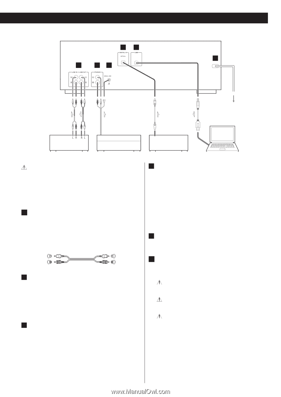
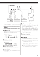
AD-RW900 (back side) D A B C E F Optical digital cable Wall socket Computer Ampli er REC PLAY (OUT) (IN) TAPE/MD/CD-R After all connections are complete, connect the power cord's plug to the AC wall socket. < Read the instructions of each device that you intend to use with this unit. < Be sure to connect each plug securely. To avoid hum and noise, do not bundle the connection cords. A LINE IN/OUT jacks These jacks transmit an analog 2-channel audio signal. Connect the components using the included RCA pin cables. Be sure to connect: White plug e White jack (L: left channel) Red plug e Red jack (R: right channel) White (L) Red (R) White (L) Red (R) B PHONO jacks [PHONO] Connect the turntable's RCA pin cable to the PHONO jacks. Be sure to connect: White plug e White jack (L: left channel) Red plug e Red jack (R: right channel) < Moving Magnet (MM) cartridges can be used for this unit. C SIGNAL GND [SIGNAL GND] Connect the ground lead of the turntable to this terminal. < This is not a safety earth. < If the turntable's ground lead is not connected to this terminal, hum noise may be heard. RCA cables RCA cables Turntable USB cable CD Player, MD Deck, etc. DIGITAL OUT D DIGITAL IN terminal [DIGITAL IN] To record digital audio signals, connect this terminal to the digital output terminal of a digital device such as a CD player with a commercially available optical digital cable. If the sampling frequency of the input digital signal is changed while an optical digital cable is connected, it might not be recognized correctly. ("OPTICAL UNLOCK" will appear on screen.) If this occurs, disconnect the optical digital cable from the connector once and reconnect it after changing the frequency. Alternately, after changing the frequency, you can turn the power off once and then turn it on again. E USB port (B-type) [USB] Connect this to a computer USB port to convert sound from this unit to a digital signal and output it to the computer. F AC Power Cord After all other connections are complete, connect the plug to an AC wall outlet. If you do not use this unit for a long period of time, unplug the power cord from the wall outlet. Be sure to connect the power cord to an AC outlet that supplies the correct voltage. Hold the power plug when plugging it into an outlet or unplugging it. Never pull or yank on the power cord. 11
-
 1
1 -
2
-
3
-
4
-
5
-
 6
6 -
 7
7 -
 8
8 -
 9
9 -
 10
10 -
 11
11 -
 12
12 -
 13
13 -
 14
14 -
 15
15 -
 16
16 -
17
-
18
-
19
-
20
-
21
-
22
-
23
-
24
-
25
-
26
-
27
-
28
-
29
-
30
-
31
-
32
-
33
-
34
-
35
-
36
-
37
-
38
-
39
-
40
-
41
-
42
-
43
-
44
-
45
-
46
-
47
-
48
-
49
-
50
-
51
-
52
 |
 |