TP-Link T2600G-28MPS T2600G-28MPSUN V1 User Guide - Page 304
PPPoE
 |
View all TP-Link T2600G-28MPS manuals
Add to My Manuals
Save this manual to your list of manuals |
Page 304 highlights
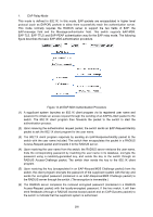
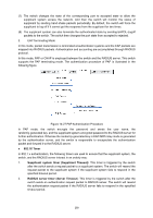
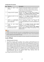
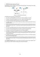
Configuration Procedure: Step Operation Description 1 Install the 802.1X client Required. For the client computers, you are required to software. install the TP-LINK 802.1X Client provided on the CD. Please refer to the software guide in the same directory with the software for more information. 2 Configure the 802.1X globally. Required. By default, the global 802.1X function is disabled. On the Network Security→802.1X→Global Config page, configure the 802.1X function globally. 3 Configure the 802.1X for the Required. On the Network Security→802.1X→Port port. Config page, configure the 802.1X feature for the port of the switch basing on the actual network. 4 Connect an authentication Required. Record the information of the client in the LAN server to the switch and do to the authentication server and configure the some configuration. corresponding authentication username and password for the client. 5 Enable the AAA function Required. On the Network Security→AAA→Global globally. Conifg page, enable the AAA function globally. 6 Configure the parameters of Required. On the Network Security→AAA→RADIUS the authentication server. Server Conifg page, configure the parameters of the RADIUS server. Note: 1. The 802.1X function takes effect only when it is enabled globally on the switch and for the port. 2. The 802.1X function cannot be enabled for LAG member ports. That is, the port with 802.1X function enabled cannot be added to the LAG. 3. The 802.1X function should not be enabled for the port connected to the authentication server. 14.10 PPPoE PPPoE ID-Insertion Overview The PPPoE ID-Insertion feature provides a way to extract a Vendor-specific tag as an identifier for the authentication, authorization, and accounting (AAA) access requests on an Ethernet interface. When enabled, the switch attaches a tag to the PPPoE discovery packets, which is called the PPPoE Vendor-Specific tag and it contains a unique line identifier. There are two formats of Vendor-specific tags: Circuit-ID format and Remote-ID format. The BRAS receives the tagged packet, decodes the tag, and uses the Circuit-ID/Remote-ID field of that tag as a NAS-Port-ID attribute in the RADIUS server for PPP authentication and AAA (authentication, authorization, and accounting) access requests. The switch will remove the Circuit-ID/Remote-ID tag from the received PPPoE Active Discovery Offer and Session-confirmation packets from the BRAS. In this Chapter the switch will work as a DSLAM. 293
-
 1
1 -
2
-
3
-
4
-
5
-
6
-
7
-
8
-
9
-
10
-
11
-
12
-
13
-
14
-
15
-
16
-
17
-
18
-
19
-
20
-
21
-
22
-
23
-
24
-
25
-
26
-
27
-
28
-
29
-
30
-
31
-
32
-
33
-
34
-
35
-
36
-
37
-
38
-
39
-
40
-
41
-
42
-
43
-
44
-
45
-
46
-
47
-
48
-
49
-
50
-
51
-
52
-
53
-
54
-
55
-
56
-
57
-
58
-
59
-
60
-
61
-
62
-
63
-
64
-
65
-
66
-
67
-
68
-
69
-
70
-
71
-
72
-
73
-
74
-
75
-
76
-
77
-
78
-
79
-
80
-
81
-
82
-
83
-
84
-
85
-
86
-
87
-
88
-
89
-
90
-
91
-
92
-
93
-
94
-
95
-
96
-
97
-
98
-
99
-
100
-
101
-
102
-
103
-
104
-
105
-
106
-
107
-
108
-
109
-
110
-
111
-
112
-
113
-
114
-
115
-
116
-
117
-
118
-
119
-
120
-
121
-
122
-
123
-
124
-
125
-
126
-
127
-
128
-
129
-
130
-
131
-
132
-
133
-
134
-
135
-
136
-
137
-
138
-
139
-
140
-
141
-
142
-
143
-
144
-
145
-
146
-
147
-
148
-
149
-
150
-
151
-
152
-
153
-
154
-
155
-
156
-
157
-
158
-
159
-
160
-
161
-
162
-
163
-
164
-
165
-
166
-
167
-
168
-
169
-
170
-
171
-
172
-
173
-
174
-
175
-
176
-
177
-
178
-
179
-
180
-
181
-
182
-
183
-
184
-
185
-
186
-
187
-
188
-
189
-
190
-
191
-
192
-
193
-
194
-
195
-
196
-
197
-
198
-
199
-
200
-
201
-
202
-
203
-
204
-
205
-
206
-
207
-
208
-
209
-
210
-
211
-
212
-
213
-
214
-
215
-
216
-
217
-
218
-
219
-
220
-
221
-
222
-
223
-
224
-
225
-
226
-
227
-
228
-
229
-
230
-
231
-
232
-
233
-
234
-
235
-
236
-
237
-
238
-
239
-
240
-
241
-
242
-
243
-
244
-
245
-
246
-
247
-
248
-
249
-
250
-
251
-
252
-
253
-
254
-
255
-
256
-
257
-
258
-
259
-
260
-
261
-
262
-
263
-
264
-
265
-
266
-
267
-
268
-
269
-
270
-
271
-
272
-
273
-
274
-
275
-
276
-
277
-
278
-
279
-
280
-
281
-
282
-
283
-
284
-
285
-
286
-
287
-
288
-
289
-
290
-
291
-
292
-
293
-
294
-
295
-
296
-
297
-
298
-
 299
299 -
 300
300 -
 301
301 -
 302
302 -
 303
303 -
 304
304 -
 305
305 -
 306
306 -
 307
307 -
 308
308 -
 309
309 -
310
-
311
-
312
-
313
-
314
-
315
-
316
-
317
-
318
-
319
-
320
-
321
-
322
-
323
-
324
-
325
-
326
-
327
-
328
-
329
-
330
-
331
-
332
-
333
-
334
-
335
-
336
-
337
-
338
-
339
-
340
-
341
-
342
-
343
-
344
-
345
-
346
-
347
-
348
-
349
-
350
-
351
-
352
-
353
-
354
-
355
-
356
-
357
-
358
-
359
-
360
-
361
-
362
-
363
-
364
 |
 |