TP-Link TL-SG3109 User Guide - Page 17
Back Panel, 2.6 Device Hardware Interfaces, 2.6.1 RJ-45 Base-T Fast Ethernet Ports
 |
UPC - 845973020484
View all TP-Link TL-SG3109 manuals
Add to My Manuals
Save this manual to your list of manuals |
Page 17 highlights
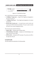
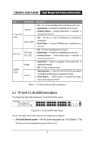
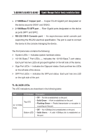
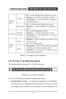
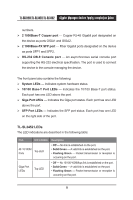
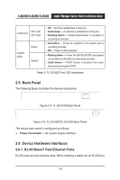
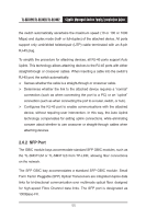
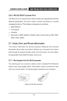
TL-SG3109/TL-SL3428/TL-SL3452 Gigabit Managed Switch Family Installation Guide SFP Link/ 2-SFP Port ACT LED System LEDs Power System • Off - No link is established on the port. • Solid Green - A valid link is established on the port. • Flashing Green - Packet transmission or reception is occurring on the port. • Solid Red - Power is supplied to the switch and is operating normally. • Off - Power is disconnected. • Flashing Green - Power On Self Test (POST) has passed successfully and the device is operating normally. • Solid Green - POST failure. A problem has been discovered during the POST. Table 3: TL-SL3452 Port LED Indications 2.5 Back Panel The following figure illustrates the devices back panel. Figure 2-4: TL-SG3109 Back Panel Figure 2-5: TL-SL3428/TL-SL3452 Back Panel The device back panel is configured as follows: Power Connector - AC power supply interface. 2.6 Device Hardware Interfaces 2.6.1 RJ-45 Base-T Fast Ethernet Ports RJ-45 ports are auto-sensing ports. When inserting a cable into an RJ-45 port, 10
-
 1
1 -
2
-
3
-
4
-
5
-
6
-
7
-
8
-
9
-
10
-
11
-
 12
12 -
 13
13 -
 14
14 -
 15
15 -
 16
16 -
 17
17 -
 18
18 -
 19
19 -
 20
20 -
 21
21 -
 22
22 -
23
-
24
-
25
-
26
-
27
-
28
-
29
-
30
-
31
-
32
-
33
-
34
-
35
-
36
-
37
-
38
-
39
-
40
-
41
-
42
-
43
-
44
-
45
-
46
-
47
-
48
-
49
-
50
-
51
-
52
-
53
-
54
 |
 |
