TP-Link TL-SG3109 User Guide - Page 19
RS-232 DB-9 Console Port, 2.7 Cable, Port, and Pinout Information
 |
UPC - 845973020484
View all TP-Link TL-SG3109 manuals
Add to My Manuals
Save this manual to your list of manuals |
Page 19 highlights
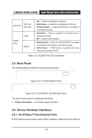
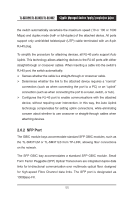
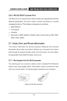
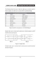
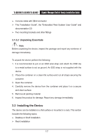
TL-SG3109/TL-SL3428/TL-SL3452 Gigabit Managed Switch Family Installation Guide 2.6.3 RS-232 DB-9 Console Port The DB-9 port is an asynchronous serial console port supporting the RS-232 electrical specification. The port is used to connect the device to a console managing the device. This interface configuration is as follows: Eight data bits. One stop bit. No parity. Baud rate is 38400 (default). Possible values of baud rate are 2400, 4800, 9600, 19200, 38400. 2.7 Cable, Port, and Pinout Information This section describes the devices physical interfaces and provides information about cable connections. Stations are connected to the device ports through the physical interface ports on the front panel. For each station, the appropriate mode (Half/Full Duplex, Auto) is set. 2.7.1 Pin Explain For RJ-45 Connector The switching port can connect to stations wired in standard RJ-45 Ethernet station mode using straight cables. Transmission devices connected to each other use crossed cables. The following figure illustrates the pin allocation: 1 2 3 4 5 6 7 8 87654321 Figure 2-6 RJ-45 connector 12
-
 1
1 -
2
-
3
-
4
-
5
-
6
-
7
-
8
-
9
-
10
-
11
-
12
-
13
-
 14
14 -
 15
15 -
 16
16 -
 17
17 -
 18
18 -
 19
19 -
 20
20 -
 21
21 -
 22
22 -
 23
23 -
 24
24 -
25
-
26
-
27
-
28
-
29
-
30
-
31
-
32
-
33
-
34
-
35
-
36
-
37
-
38
-
39
-
40
-
41
-
42
-
43
-
44
-
45
-
46
-
47
-
48
-
49
-
50
-
51
-
52
-
53
-
54
 |
 |
