Thermador HMWB36WS Installation Instructions - Page 14
Wall installation, Mounting the hood
 |
View all Thermador HMWB36WS manuals
Add to My Manuals
Save this manual to your list of manuals |
Page 14 highlights
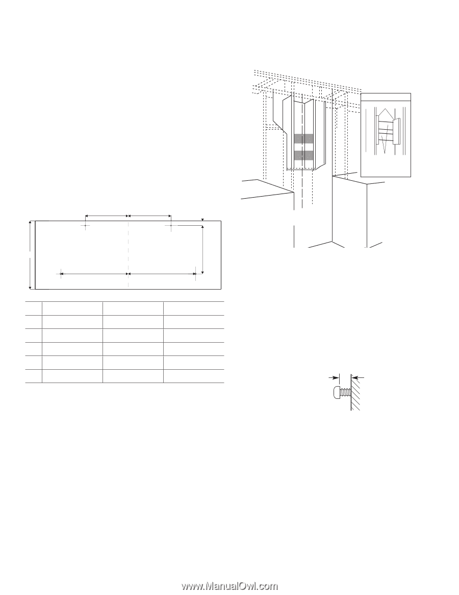
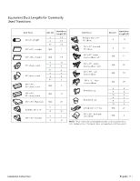
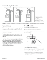
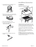
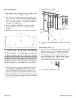
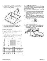
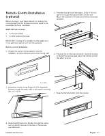
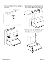
Wall installation 1. Turn power OFF at the service panel. Lock service panel to prevent power from being turned ON. 2. After the hood installation height has been determined, draw a horizontal line at a distance above the cooktop equal to the recommended hood installation height plus 10 4⁄16'' (260 mm). This line is the mounting location of the upper mounting screws. 3. Find the centerline of the hood. Draw a vertical line along this centerline up to the horizontal line drawn in Step 2. 4. Mark the screw hole locations indicated in the diagram. 7. Reinstall drywall and inish. IMPORTANT: Framing must be capable of supporting 100 lbs. View from rear Cleats Mounting Support Center A Line A E Centerline of Installation space WALL D C B B 30" (76.2 cm) 36" (91.4 cm) 48" (121.9 cm) A 615⁄16" (17.5 cm) 114⁄16" (28.5 cm) 114⁄16" (28.5 cm) B 1013⁄16" (27.5 cm) 1013⁄16" (27.5 cm) 1013⁄16" (27.5 cm) C 1015⁄16" (27.8 cm) 1015⁄16" (27.8 cm) 1015⁄16" (27.8 cm) D 73⁄4" (19.7 cm) 73⁄4" (19.7 cm) 73⁄4" (19.7 cm) E 13⁄16" (2 cm) 13⁄16" (2 cm) 13⁄16" (2 cm) 8. Cut holes at marked locations for duct and electrical wiring. Mounting the hood 1. Drive a mounting screw (from the hardware package) partway into each center of the narrow neck of the keyhole slots marked on the wall's support frame. 2. Install the 2 pieces of the selected screws on the mountings screws location (see the image). Leave a 1⁄4'' (6.4 mm) gap between the wall and the back of the screw head to slide range hood into place. 1/4" (6.4) 5. If drywall is present, cut away enough drywall to expose 2 vertical studs at the indicated holes location. Install two horizontal supports between two wall studs at the bottom and upper mounting holes installation location. 6. The horizontal support must be lush with the room side of the studs. Use cleats behind both sides of the support to secure wall studs. 3. Fix the wiring conduit of the hood. English | 14 | Installation Instructions
-
 1
1 -
2
-
3
-
4
-
5
-
6
-
7
-
8
-
 9
9 -
 10
10 -
 11
11 -
 12
12 -
 13
13 -
 14
14 -
 15
15 -
 16
16 -
 17
17 -
 18
18 -
 19
19 -
20
-
21
-
22
-
23
-
24
-
25
-
26
-
27
-
28
-
29
-
30
-
31
-
32
-
33
-
34
-
35
-
36
-
37
-
38
-
39
-
40
-
41
-
42
-
43
-
44
-
45
-
46
-
47
-
48
-
49
-
50
-
51
-
52
-
53
-
54
-
55
-
56
-
57
-
58
-
59
-
60
 |
 |