Thermador HMWB36WS Installation Instructions - Page 15
Cabinet Installation
 |
View all Thermador HMWB36WS manuals
Add to My Manuals
Save this manual to your list of manuals |
Page 15 highlights
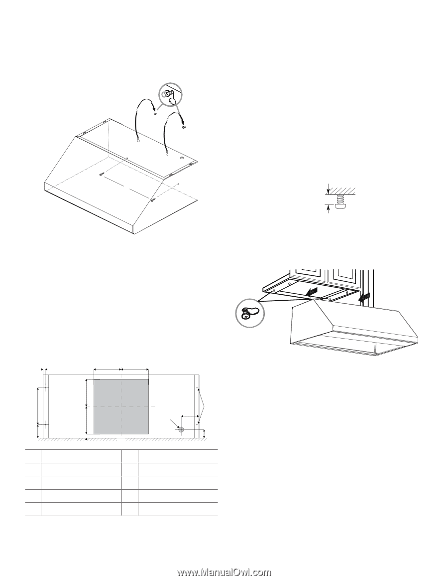
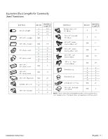
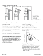
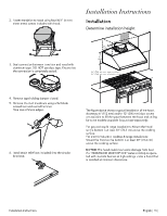
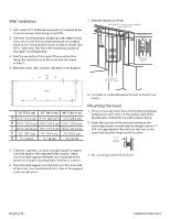
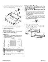
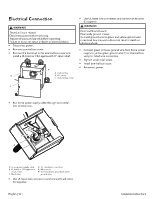
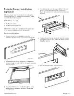
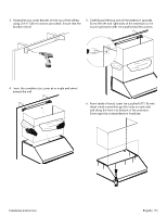
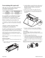
4. Slide the hood back against the wall. Tighten the mounting screws. Be sure the screw heads are in the narrow neck of the keyhole slot. A B For recessed bottom cabinet only If the cabinets have front, side or back trim, make 2 wood shims the width of the trim and attach them to the cabinet bottom recess on both sides. NOTE: Your cabinet must be able to support at least 88 lb (40 kg). • Drive a mounting screw (from the hardware package) partway into each center of the narrow neck of the keyhole slots marked on the cabinet bottom or the wall's support frame. • Install 4 - 4 x 8 mm mounting screws on the mountings screws location (see the image). Leave a 1⁄4'' (6.4 mm) gap between the wall and the back of the screw head to slide range hood into place. 1/4" (6.4 mm) 5. Drive 2 pieces of the selected screws in the lower security screws location (see the image above). 6. Connect Ductwork to hood. Cabinet Installation Turn power OFF at the service panel. Lock service panel to prevent power from being turned ON. Cabinet cutouts 1. Use the diagram or the hood as a template and mark the locations on the cabinet for ductwork, electrical wiring and keyhole screw slots. C A Center Line A Front face of the cabinet A D A E B Wall A 54⁄16" (13.3 cm) F B 3⁄4" (1.9 cm) G C 6⁄16" (1 cm) H D 71⁄16" (18 cm) I E 29⁄16" (6.5 cm) Bottom face of the cabinet H F I G 37⁄16" (8.7 cm) 11⁄2" (4 cm) 1" (2.54 cm) 3⁄16" (.5 cm) • Fix the wiring conduit of the hood. • Slide the hood back against the cabinet. Tighten the mounting screws. Be sure the screw heads are in the narrow neck of the keyhole slot. A Installation Instructions English | 15 |
-
 1
1 -
2
-
3
-
4
-
5
-
6
-
7
-
8
-
9
-
 10
10 -
 11
11 -
 12
12 -
 13
13 -
 14
14 -
 15
15 -
 16
16 -
 17
17 -
 18
18 -
 19
19 -
 20
20 -
21
-
22
-
23
-
24
-
25
-
26
-
27
-
28
-
29
-
30
-
31
-
32
-
33
-
34
-
35
-
36
-
37
-
38
-
39
-
40
-
41
-
42
-
43
-
44
-
45
-
46
-
47
-
48
-
49
-
50
-
51
-
52
-
53
-
54
-
55
-
56
-
57
-
58
-
59
-
60
 |
 |