Toshiba A205-S4777 Maintenance Manual - Page 154
Installing the FL Inverter Board
 |
UPC - 032017913844
View all Toshiba A205-S4777 manuals
Add to My Manuals
Save this manual to your list of manuals |
Page 154 highlights
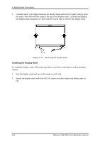
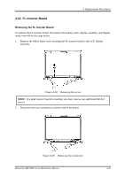
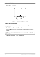
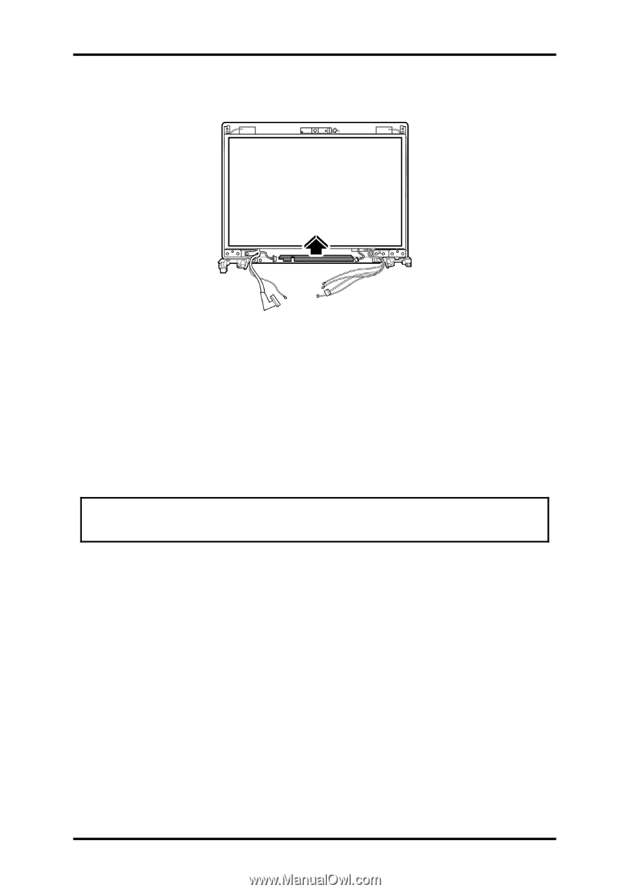
4 Replacement Procedures 3. Remove the FL inverter board. Figure 4-40 Removing the FL inverter board Installing the FL Inverter Board To install the FL inverter board, follow the steps below and refer to the figure in the preceding section. 1. Place the FL inverter board on the LCD module. 2. Secure one M2x3 black screw connecting the FL inverter board to the LCD display assembly. NOTE: If a dual inverter board is installed, you must secure it with two additional M2.5x4 screws. 3. Connect the two connectors on either side of the board. 4-36 Minnesota 10M/10MG Series Maintenance Manual
-
 1
1 -
2
-
3
-
4
-
5
-
6
-
7
-
8
-
9
-
10
-
11
-
12
-
13
-
14
-
15
-
16
-
17
-
18
-
19
-
20
-
21
-
22
-
23
-
24
-
25
-
26
-
27
-
28
-
29
-
30
-
31
-
32
-
33
-
34
-
35
-
36
-
37
-
38
-
39
-
40
-
41
-
42
-
43
-
44
-
45
-
46
-
47
-
48
-
49
-
50
-
51
-
52
-
53
-
54
-
55
-
56
-
57
-
58
-
59
-
60
-
61
-
62
-
63
-
64
-
65
-
66
-
67
-
68
-
69
-
70
-
71
-
72
-
73
-
74
-
75
-
76
-
77
-
78
-
79
-
80
-
81
-
82
-
83
-
84
-
85
-
86
-
87
-
88
-
89
-
90
-
91
-
92
-
93
-
94
-
95
-
96
-
97
-
98
-
99
-
100
-
101
-
102
-
103
-
104
-
105
-
106
-
107
-
108
-
109
-
110
-
111
-
112
-
113
-
114
-
115
-
116
-
117
-
118
-
119
-
120
-
121
-
122
-
123
-
124
-
125
-
126
-
127
-
128
-
129
-
130
-
131
-
132
-
133
-
134
-
135
-
136
-
137
-
138
-
139
-
140
-
141
-
142
-
143
-
144
-
145
-
146
-
147
-
148
-
 149
149 -
 150
150 -
 151
151 -
 152
152 -
 153
153 -
 154
154 -
 155
155 -
 156
156 -
 157
157 -
 158
158 -
 159
159 -
160
-
161
-
162
-
163
-
164
-
165
-
166
-
167
-
168
-
169
-
170
-
171
-
172
-
173
-
174
-
175
-
176
-
177
-
178
-
179
-
180
-
181
-
182
-
183
-
184
-
185
-
186
-
187
-
188
-
189
-
190
-
191
-
192
-
193
-
194
-
195
-
196
-
197
-
198
-
199
-
200
-
201
-
202
-
203
-
204
-
205
-
206
-
207
-
208
-
209
-
210
-
211
-
212
-
213
-
214
-
215
-
216
-
217
-
218
-
219
-
220
-
221
-
222
-
223
-
224
-
225
-
226
-
227
-
228
-
229
-
230
-
231
-
232
-
233
-
234
-
235
-
236
-
237
-
238
-
239
-
240
-
241
-
242
-
243
 |
 |
4
Replacement Procedures
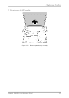
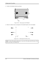
3.
Remove the FL inverter board.
Figure 4-40
Removing the FL inverter board
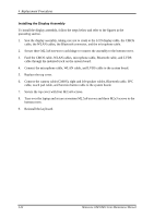
Installing the FL Inverter Board
To install the FL inverter board, follow the steps below and refer to the figure in the
preceding section.
1.
Place the FL inverter board on the LCD module.
2.
Secure one M2x3 black screw connecting the FL inverter board to the LCD display
assembly.
NOTE
:
If a dual inverter board is installed, you must secure it with two additional
M2.5x4 screws.
3.
Connect the two connectors on either side of the board.
4-36
Minnesota 10M/10MG Series Maintenance Manual