Toshiba A205-S4777 Maintenance Manual - Page 159
Camera and Microphone
 |
UPC - 032017913844
View all Toshiba A205-S4777 manuals
Add to My Manuals
Save this manual to your list of manuals |
Page 159 highlights
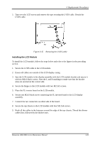
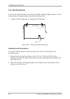
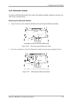
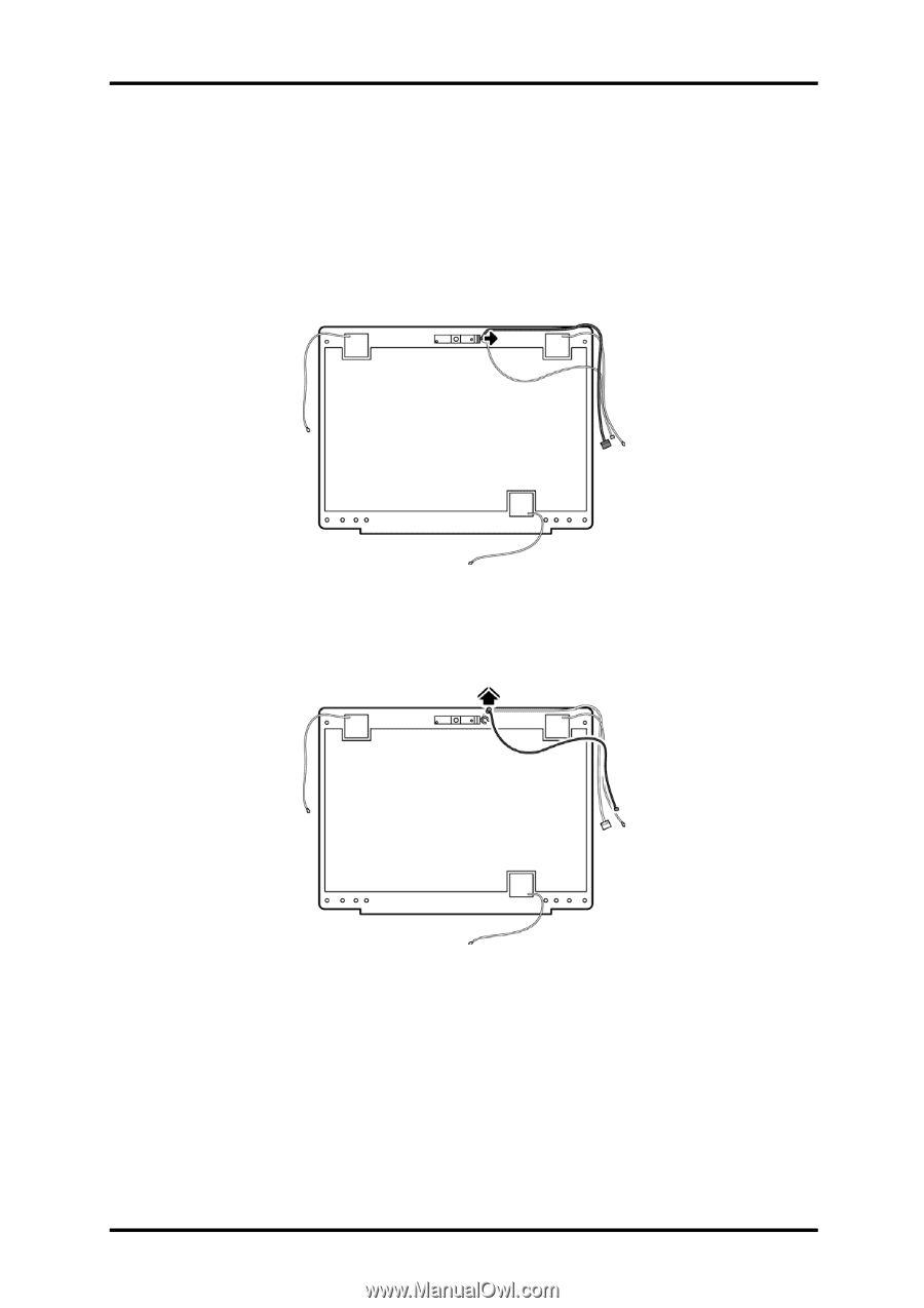
4 Replacement Procedures 4.15 Camera and Microphone To remove the camera and microphone, first remove the display assembly, display mask, FL inverter board and the LCD display module. Then follow the steps below. 1. Remove the CMOS cable from the camera module. Remove the camera module by gently peeling it away from its adhesive backing. Figure 4-47 Removing the CMOS cable & camera 2. Use a flat screwdriver to lever the microphone module from its bracket and gently lift out. Figure 4-48 Removing the microphone Minnesota 10M/10MG Series Maintenance Manual 4-41
-
 1
1 -
2
-
3
-
4
-
5
-
6
-
7
-
8
-
9
-
10
-
11
-
12
-
13
-
14
-
15
-
16
-
17
-
18
-
19
-
20
-
21
-
22
-
23
-
24
-
25
-
26
-
27
-
28
-
29
-
30
-
31
-
32
-
33
-
34
-
35
-
36
-
37
-
38
-
39
-
40
-
41
-
42
-
43
-
44
-
45
-
46
-
47
-
48
-
49
-
50
-
51
-
52
-
53
-
54
-
55
-
56
-
57
-
58
-
59
-
60
-
61
-
62
-
63
-
64
-
65
-
66
-
67
-
68
-
69
-
70
-
71
-
72
-
73
-
74
-
75
-
76
-
77
-
78
-
79
-
80
-
81
-
82
-
83
-
84
-
85
-
86
-
87
-
88
-
89
-
90
-
91
-
92
-
93
-
94
-
95
-
96
-
97
-
98
-
99
-
100
-
101
-
102
-
103
-
104
-
105
-
106
-
107
-
108
-
109
-
110
-
111
-
112
-
113
-
114
-
115
-
116
-
117
-
118
-
119
-
120
-
121
-
122
-
123
-
124
-
125
-
126
-
127
-
128
-
129
-
130
-
131
-
132
-
133
-
134
-
135
-
136
-
137
-
138
-
139
-
140
-
141
-
142
-
143
-
144
-
145
-
146
-
147
-
148
-
149
-
150
-
151
-
152
-
153
-
 154
154 -
 155
155 -
 156
156 -
 157
157 -
 158
158 -
 159
159 -
 160
160 -
 161
161 -
 162
162 -
 163
163 -
 164
164 -
165
-
166
-
167
-
168
-
169
-
170
-
171
-
172
-
173
-
174
-
175
-
176
-
177
-
178
-
179
-
180
-
181
-
182
-
183
-
184
-
185
-
186
-
187
-
188
-
189
-
190
-
191
-
192
-
193
-
194
-
195
-
196
-
197
-
198
-
199
-
200
-
201
-
202
-
203
-
204
-
205
-
206
-
207
-
208
-
209
-
210
-
211
-
212
-
213
-
214
-
215
-
216
-
217
-
218
-
219
-
220
-
221
-
222
-
223
-
224
-
225
-
226
-
227
-
228
-
229
-
230
-
231
-
232
-
233
-
234
-
235
-
236
-
237
-
238
-
239
-
240
-
241
-
242
-
243
 |
 |
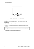
4
Replacement Procedures
4.15 Camera and Microphone
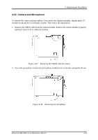
To remove the camera and microphone, first remove the display assembly, display mask, FL
inverter board and the LCD display module. Then follow the steps below.
1.
Remove the CMOS cable from the camera module. Remove the camera module by gently
peeling it away from its adhesive backing.
Figure 4-47
Removing the CMOS cable & camera
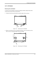
2.
Use a flat screwdriver to lever the microphone module from its bracket and gently lift out.
Figure 4-48
Removing the microphone
Minnesota 10M/10MG Series Maintenance Manual
4-41