Toshiba A205-S4777 Maintenance Manual - Page 40
Procedure 1, Power Status Check
 |
UPC - 032017913844
View all Toshiba A205-S4777 manuals
Add to My Manuals
Save this manual to your list of manuals |
Page 40 highlights
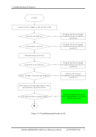
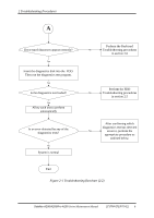
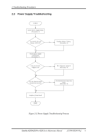
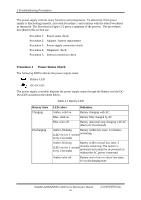
2 Troubleshooting Procedures The power supply controls many functions and components. To determine if the power supply is functioning properly, start with Procedure 1 and continue with the other Procedures as instructed. The flowchart in Figure 2-2 gives a summary of the process. The procedures described in this section are: Procedure 1: Power status check Procedure 2: Adaptor / battery replacement Procedure 3: Power supply connection check Procedure 4: Diagnostic check Procedure 5: Internal connection check Procedure 1 Power Status Check The following LEDS indicate the power supply status: Battery LED DC-IN LED The power supply controller displays the power supply status through the Battery and the DCIN LEDS as listed in the tables below. Table 2-1 Battery LED Battery State Charging Discharging LED colors Definition Amber, solid on Battery charging with AC. Blue, solid on Battery fully charged by AC Blue color off Battery abnormal stop charging with AC (Bad cell/ Overheated) Amber, blinking Battery within low state: 12 minutes (LED on for 1 second remaining every 4 seconds) Amber, blinking Battery within critical low state: 3 (LED on for 1 second minutes remaining. The system is every 2 seconds) protected and cannot be re-powered on without the AC power connected. Amber color off Battery not in low or critical low state; It's in discharging state Satellite A200/A205/Pro A200 Series Maintenance Manual 10 [CONFIDENTIAL]
-
 1
1 -
2
-
3
-
4
-
5
-
6
-
7
-
8
-
9
-
10
-
11
-
12
-
13
-
14
-
15
-
16
-
17
-
18
-
19
-
20
-
21
-
22
-
23
-
24
-
25
-
26
-
27
-
28
-
29
-
30
-
31
-
32
-
33
-
34
-
 35
35 -
 36
36 -
 37
37 -
 38
38 -
 39
39 -
 40
40 -
 41
41 -
 42
42 -
 43
43 -
 44
44 -
 45
45 -
46
-
47
-
48
-
49
-
50
-
51
-
52
-
53
-
54
-
55
-
56
-
57
-
58
-
59
-
60
-
61
-
62
-
63
-
64
-
65
-
66
-
67
-
68
-
69
-
70
-
71
-
72
-
73
-
74
-
75
-
76
-
77
-
78
-
79
-
80
-
81
-
82
-
83
-
84
-
85
-
86
-
87
-
88
-
89
-
90
-
91
-
92
-
93
-
94
-
95
-
96
-
97
-
98
-
99
-
100
-
101
-
102
-
103
-
104
-
105
-
106
-
107
-
108
-
109
-
110
-
111
-
112
-
113
-
114
-
115
-
116
-
117
-
118
-
119
-
120
-
121
-
122
-
123
-
124
-
125
-
126
-
127
-
128
-
129
-
130
-
131
-
132
-
133
-
134
-
135
-
136
-
137
-
138
-
139
-
140
-
141
-
142
-
143
-
144
-
145
-
146
-
147
-
148
-
149
-
150
-
151
-
152
-
153
-
154
-
155
-
156
-
157
-
158
-
159
-
160
-
161
-
162
-
163
-
164
-
165
-
166
-
167
-
168
-
169
-
170
-
171
-
172
-
173
-
174
-
175
-
176
-
177
-
178
-
179
-
180
-
181
-
182
-
183
-
184
-
185
-
186
-
187
-
188
-
189
-
190
-
191
-
192
-
193
-
194
-
195
-
196
-
197
-
198
-
199
-
200
-
201
-
202
-
203
-
204
-
205
-
206
-
207
-
208
-
209
-
210
-
211
-
212
-
213
-
214
-
215
-
216
-
217
-
218
-
219
-
220
-
221
-
222
-
223
-
224
-
225
-
226
-
227
-
228
-
229
-
230
-
231
-
232
-
233
-
234
-
235
-
236
-
237
-
238
-
239
-
240
-
241
-
242
-
243
 |
 |