Toshiba A205-S4777 Maintenance Manual - Page 155
LCD Module
 |
UPC - 032017913844
View all Toshiba A205-S4777 manuals
Add to My Manuals
Save this manual to your list of manuals |
Page 155 highlights
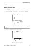
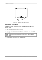
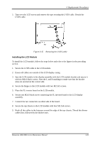
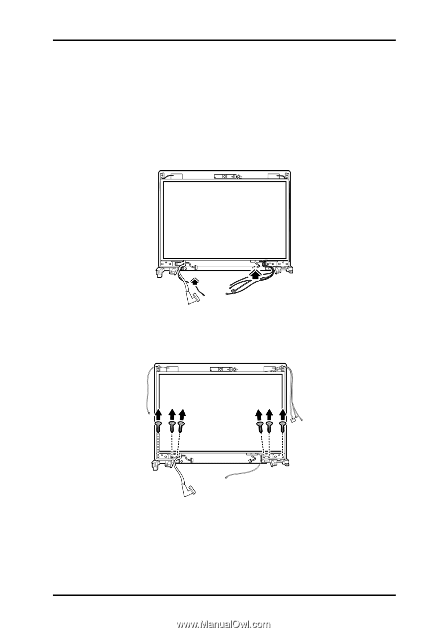
4 Replacement Procedures 4.13 LCD Module Removing the LCD Module To remove the LCD module, first remove the display assembly, display mask, and FL inverter board and then follow the steps below. 1. Unhook all cables from the fasteners around the edge of the top chassis. Figure 4-41 Removing the LCD Module 2. Remove four M2.5x4 screws securing the top chassis to the LCD module, and two M2.5x5 screws securing the hinges to the LCD module. Figure 4-42 Removing the LCD Module Minnesota 10M/10MG Series Maintenance Manual 4-37
-
 1
1 -
2
-
3
-
4
-
5
-
6
-
7
-
8
-
9
-
10
-
11
-
12
-
13
-
14
-
15
-
16
-
17
-
18
-
19
-
20
-
21
-
22
-
23
-
24
-
25
-
26
-
27
-
28
-
29
-
30
-
31
-
32
-
33
-
34
-
35
-
36
-
37
-
38
-
39
-
40
-
41
-
42
-
43
-
44
-
45
-
46
-
47
-
48
-
49
-
50
-
51
-
52
-
53
-
54
-
55
-
56
-
57
-
58
-
59
-
60
-
61
-
62
-
63
-
64
-
65
-
66
-
67
-
68
-
69
-
70
-
71
-
72
-
73
-
74
-
75
-
76
-
77
-
78
-
79
-
80
-
81
-
82
-
83
-
84
-
85
-
86
-
87
-
88
-
89
-
90
-
91
-
92
-
93
-
94
-
95
-
96
-
97
-
98
-
99
-
100
-
101
-
102
-
103
-
104
-
105
-
106
-
107
-
108
-
109
-
110
-
111
-
112
-
113
-
114
-
115
-
116
-
117
-
118
-
119
-
120
-
121
-
122
-
123
-
124
-
125
-
126
-
127
-
128
-
129
-
130
-
131
-
132
-
133
-
134
-
135
-
136
-
137
-
138
-
139
-
140
-
141
-
142
-
143
-
144
-
145
-
146
-
147
-
148
-
149
-
 150
150 -
 151
151 -
 152
152 -
 153
153 -
 154
154 -
 155
155 -
 156
156 -
 157
157 -
 158
158 -
 159
159 -
 160
160 -
161
-
162
-
163
-
164
-
165
-
166
-
167
-
168
-
169
-
170
-
171
-
172
-
173
-
174
-
175
-
176
-
177
-
178
-
179
-
180
-
181
-
182
-
183
-
184
-
185
-
186
-
187
-
188
-
189
-
190
-
191
-
192
-
193
-
194
-
195
-
196
-
197
-
198
-
199
-
200
-
201
-
202
-
203
-
204
-
205
-
206
-
207
-
208
-
209
-
210
-
211
-
212
-
213
-
214
-
215
-
216
-
217
-
218
-
219
-
220
-
221
-
222
-
223
-
224
-
225
-
226
-
227
-
228
-
229
-
230
-
231
-
232
-
233
-
234
-
235
-
236
-
237
-
238
-
239
-
240
-
241
-
242
-
243
 |
 |
4
Replacement Procedures
4.13 LCD Module
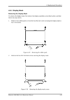
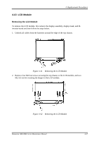
Removing the LCD Module
To remove the LCD module, first remove the display assembly, display mask, and FL
inverter board and then follow the steps below.
1.
Unhook all cables from the fasteners around the edge of the top chassis.
Figure 4-41
Removing the LCD Module
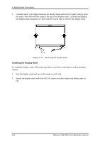
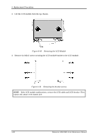
2.
Remove four M2.5x4 screws securing the top chassis to the LCD module, and two
M2.5x5 screws securing the hinges to the LCD module.
Figure 4-42
Removing the LCD Module
Minnesota 10M/10MG Series Maintenance Manual
4-37