Toshiba A205-S4777 Maintenance Manual - Page 178
System Board
 |
UPC - 032017913844
View all Toshiba A205-S4777 manuals
Add to My Manuals
Save this manual to your list of manuals |
Page 178 highlights
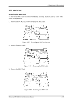
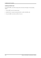
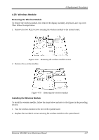
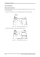
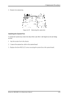
4 Replacement Procedures 4.25 System Board Removing the System Board To remove the system board, first remove the display assembly, keyboard, top cover, MDC card, USB board, wireless module, and system fan. Then follow the steps below: 1. Unhook and remove the VGA cable. Figure 4-74 Removing the VGA cable 2. Unhook the DC-IN connector from its socket. Figure 4-75 Removing the DC-IN connector 4-60 Minnesota 10M/10MG Series Maintenance Manual
-
 1
1 -
2
-
3
-
4
-
5
-
6
-
7
-
8
-
9
-
10
-
11
-
12
-
13
-
14
-
15
-
16
-
17
-
18
-
19
-
20
-
21
-
22
-
23
-
24
-
25
-
26
-
27
-
28
-
29
-
30
-
31
-
32
-
33
-
34
-
35
-
36
-
37
-
38
-
39
-
40
-
41
-
42
-
43
-
44
-
45
-
46
-
47
-
48
-
49
-
50
-
51
-
52
-
53
-
54
-
55
-
56
-
57
-
58
-
59
-
60
-
61
-
62
-
63
-
64
-
65
-
66
-
67
-
68
-
69
-
70
-
71
-
72
-
73
-
74
-
75
-
76
-
77
-
78
-
79
-
80
-
81
-
82
-
83
-
84
-
85
-
86
-
87
-
88
-
89
-
90
-
91
-
92
-
93
-
94
-
95
-
96
-
97
-
98
-
99
-
100
-
101
-
102
-
103
-
104
-
105
-
106
-
107
-
108
-
109
-
110
-
111
-
112
-
113
-
114
-
115
-
116
-
117
-
118
-
119
-
120
-
121
-
122
-
123
-
124
-
125
-
126
-
127
-
128
-
129
-
130
-
131
-
132
-
133
-
134
-
135
-
136
-
137
-
138
-
139
-
140
-
141
-
142
-
143
-
144
-
145
-
146
-
147
-
148
-
149
-
150
-
151
-
152
-
153
-
154
-
155
-
156
-
157
-
158
-
159
-
160
-
161
-
162
-
163
-
164
-
165
-
166
-
167
-
168
-
169
-
170
-
171
-
172
-
 173
173 -
 174
174 -
 175
175 -
 176
176 -
 177
177 -
 178
178 -
 179
179 -
 180
180 -
 181
181 -
 182
182 -
 183
183 -
184
-
185
-
186
-
187
-
188
-
189
-
190
-
191
-
192
-
193
-
194
-
195
-
196
-
197
-
198
-
199
-
200
-
201
-
202
-
203
-
204
-
205
-
206
-
207
-
208
-
209
-
210
-
211
-
212
-
213
-
214
-
215
-
216
-
217
-
218
-
219
-
220
-
221
-
222
-
223
-
224
-
225
-
226
-
227
-
228
-
229
-
230
-
231
-
232
-
233
-
234
-
235
-
236
-
237
-
238
-
239
-
240
-
241
-
242
-
243
 |
 |
4
Replacement Procedures
4.25 System Board
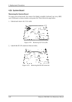
Removing the System Board
To remove the system board, first remove the display assembly, keyboard, top cover, MDC
card, USB board, wireless module, and system fan. Then follow the steps below:
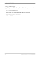
1.
Unhook and remove the VGA cable.
Figure 4-74
Removing the VGA cable
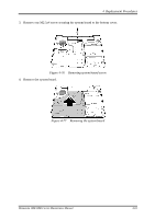
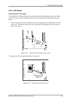
2.
Unhook the DC-IN connector from its socket.
Figure 4-75
Removing the DC-IN connector
4-60
Minnesota 10M/10MG Series Maintenance Manual