Toshiba A205-S4777 Maintenance Manual - Page 183
Installing the VGA Board
 |
UPC - 032017913844
View all Toshiba A205-S4777 manuals
Add to My Manuals
Save this manual to your list of manuals |
Page 183 highlights
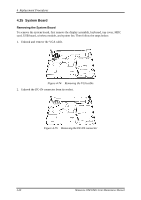
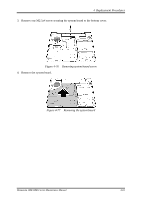
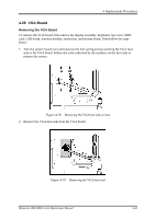
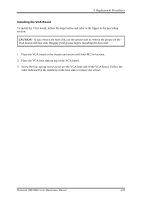
4 Replacement Procedures Installing the VGA Board To install the VGA board, follow the steps below and refer to the figure in the preceding section: CAUTION: If you remove the heat sink, use the grease tool to remove the grease on the VGA board and heat sink. Reapply fresh grease before installing the heat sink. 1. Place the VGA board in the chassis and secure with four M2.5x4 screws. 2. Place the VGA heat sink on top of the VGA board. 3. Screw the four spring screws to secure the VGA heat sink to the VGA board. Follow the order indicated by the numbers on the heat sink to remove the screws. Minnesota 10M/10MG Series Maintenance Manual 4-65
-
 1
1 -
2
-
3
-
4
-
5
-
6
-
7
-
8
-
9
-
10
-
11
-
12
-
13
-
14
-
15
-
16
-
17
-
18
-
19
-
20
-
21
-
22
-
23
-
24
-
25
-
26
-
27
-
28
-
29
-
30
-
31
-
32
-
33
-
34
-
35
-
36
-
37
-
38
-
39
-
40
-
41
-
42
-
43
-
44
-
45
-
46
-
47
-
48
-
49
-
50
-
51
-
52
-
53
-
54
-
55
-
56
-
57
-
58
-
59
-
60
-
61
-
62
-
63
-
64
-
65
-
66
-
67
-
68
-
69
-
70
-
71
-
72
-
73
-
74
-
75
-
76
-
77
-
78
-
79
-
80
-
81
-
82
-
83
-
84
-
85
-
86
-
87
-
88
-
89
-
90
-
91
-
92
-
93
-
94
-
95
-
96
-
97
-
98
-
99
-
100
-
101
-
102
-
103
-
104
-
105
-
106
-
107
-
108
-
109
-
110
-
111
-
112
-
113
-
114
-
115
-
116
-
117
-
118
-
119
-
120
-
121
-
122
-
123
-
124
-
125
-
126
-
127
-
128
-
129
-
130
-
131
-
132
-
133
-
134
-
135
-
136
-
137
-
138
-
139
-
140
-
141
-
142
-
143
-
144
-
145
-
146
-
147
-
148
-
149
-
150
-
151
-
152
-
153
-
154
-
155
-
156
-
157
-
158
-
159
-
160
-
161
-
162
-
163
-
164
-
165
-
166
-
167
-
168
-
169
-
170
-
171
-
172
-
173
-
174
-
175
-
176
-
177
-
 178
178 -
 179
179 -
 180
180 -
 181
181 -
 182
182 -
 183
183 -
 184
184 -
 185
185 -
 186
186 -
 187
187 -
 188
188 -
189
-
190
-
191
-
192
-
193
-
194
-
195
-
196
-
197
-
198
-
199
-
200
-
201
-
202
-
203
-
204
-
205
-
206
-
207
-
208
-
209
-
210
-
211
-
212
-
213
-
214
-
215
-
216
-
217
-
218
-
219
-
220
-
221
-
222
-
223
-
224
-
225
-
226
-
227
-
228
-
229
-
230
-
231
-
232
-
233
-
234
-
235
-
236
-
237
-
238
-
239
-
240
-
241
-
242
-
243
 |
 |
4
Replacement Procedures
Minnesota 10M/10MG Series Maintenance Manual
4-65
Installing the VGA Board
To install the VGA board, follow the steps below and refer to the figure in the preceding
section:
CAUTION:
If you remove the heat sink, use the grease tool to remove the grease on the
VGA board and heat sink. Reapply fresh grease before installing the heat sink.
1.
Place the VGA board in the chassis and secure with four M2.5x4 screws.
2.
Place the VGA heat sink on top of the VGA board.
3.
Screw the four spring screws to secure the VGA heat sink to the VGA board. Follow the
order indicated by the numbers on the heat sink to remove the screws.