Toshiba DVR610 Service Manual - Page 10
Installation
 |
UPC - 022265001370
View all Toshiba DVR610 manuals
Add to My Manuals
Save this manual to your list of manuals |
Page 10 highlights
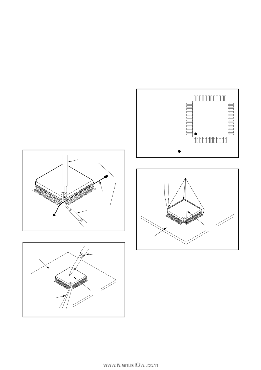
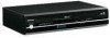
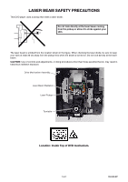
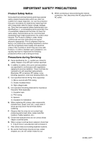
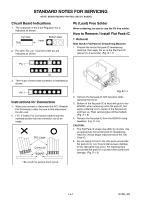
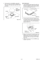
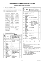
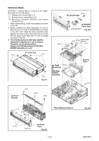
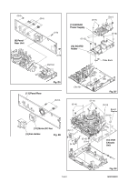
With Iron Wire: 1. Using desoldering braid, remove the solder from all pins of the flat pack-IC. When you use solder flux which is applied to all pins of the flat pack-IC, you can remove it easily. (Fig. S-1-3) 2. Affix the wire to a workbench or solid mounting point, as shown in Fig. S-1-5. 3. While heating the pins using a fine tip soldering iron or hot air blower, pull up the wire as the solder melts so as to lift the IC leads from the BOARD contact pads as shown in Fig. S-1-5. 4. Bottom of the flat pack-IC is fixed with glue to the BOARD; when removing entire flat pack-IC, first apply soldering iron to center of the flat pack-IC and heat up. Then remove (glue will be melted). (Fig. S-1-6) 5. Release the flat pack-IC from the BOARD using tweezers. (Fig. S-1-6) Note: When using a soldering iron, care must be taken to ensure that the flat pack-IC is not being held by glue. When the flat pack-IC is removed from the BOARD, handle it gently because it may be damaged if force is applied. Hot Air Blower 2. Installation 1. Using desoldering braid, remove the solder from the foil of each pin of the flat pack-IC on the BOARD so you can install a replacement flat packIC more easily. 2. The "●" mark on the flat pack-IC indicates pin 1. (See Fig. S-1-7.) Be sure this mark matches the 1 on the BOARD when positioning for installation. Then presolder the four corners of the flat pack-IC. (See Fig. S-1-8.) 3. Solder all pins of the flat pack-IC. Be sure that none of the pins have solder bridges. Example : Pin 1 of the Flat Pack-IC is indicated by a " " mark. Fig. S-1-7 or Iron Wire Presolder To Solid Mounting Point BOARD Soldering Iron Fig. S-1-5 Fine Tip Soldering Iron BOARD Flat Pack-IC Fig. S-1-8 Tweezers Flat Pack-IC Fig. S-1-6 1-4-3 DVDN_SN
-
 1
1 -
2
-
3
-
4
-
 5
5 -
 6
6 -
 7
7 -
 8
8 -
 9
9 -
 10
10 -
 11
11 -
 12
12 -
 13
13 -
 14
14 -
 15
15 -
16
-
17
-
18
-
19
-
20
-
21
-
22
-
23
-
24
-
25
-
26
-
27
-
28
-
29
-
30
-
31
-
32
-
33
-
34
-
35
-
36
-
37
-
38
-
39
-
40
-
41
-
42
-
43
-
44
-
45
-
46
-
47
-
48
-
49
-
50
-
51
-
52
-
53
-
54
-
55
-
56
-
57
-
58
-
59
-
60
-
61
-
62
-
63
-
64
-
65
-
66
-
67
-
68
-
69
-
70
-
71
-
72
-
73
-
74
-
75
-
76
-
77
-
78
-
79
-
80
-
81
-
82
-
83
-
84
-
85
-
86
-
87
 |
 |