Toshiba DVR610 Service Manual - Page 7
Safety Check after Servicing - ratings
 |
UPC - 022265001370
View all Toshiba DVR610 manuals
Add to My Manuals
Save this manual to your list of manuals |
Page 7 highlights
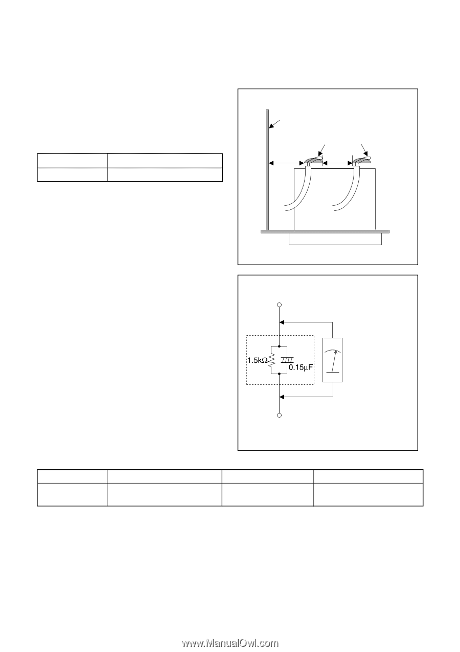
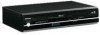
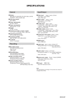
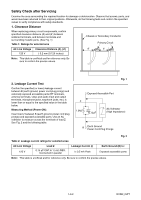
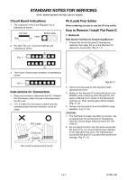
Safety Check after Servicing Examine the area surrounding the repaired location for damage or deterioration. Observe that screws, parts, and wires have been returned to their original positions. Afterwards, do the following tests and confirm the specified values to verify compliance with safety standards. 1. Clearance Distance When replacing primary circuit components, confirm specified clearance distance (d) and (d') between soldered terminals, and between terminals and surrounding metallic parts. (See Fig. 1) Table 1: Ratings for selected area AC Line Voltage 120 V Clearance Distance (d), (d') ≥ 3.2 mm (0.126 inches) Chassis or Secondary Conductor Primary Circuit d' d Note: This table is unofficial and for reference only. Be sure to confirm the precise values. 2. Leakage Current Test Confirm the specified (or lower) leakage current between B (earth ground, power cord plug prongs) and externally exposed accessible parts (RF terminals, antenna terminals, video and audio input and output terminals, microphone jacks, earphone jacks, etc.) is lower than or equal to the specified value in the table below. Measuring Method (Power ON): Insert load Z between B (earth ground, power cord plug prongs) and exposed accessible parts. Use an AC voltmeter to measure across the terminals of load Z. See Fig. 2 and the following table. Fig. 1 Exposed Accessible Part Z AC Voltmeter (High Impedance) B Earth Ground Power Cord Plug Prongs Fig. 2 Table 2: Leakage current ratings for selected areas AC Line Voltage 120 V Load Z 0.15 μF CAP. & 1.5 kΩ RES. Connected in parallel Leakage Current (i) i ≤ 0.5 mA Peak Earth Ground (B) to: Exposed accessible parts Note: This table is unofficial and for reference only. Be sure to confirm the precise values. 1-3-2 DVDN_ISPT
-
 1
1 -
 2
2 -
 3
3 -
 4
4 -
 5
5 -
 6
6 -
 7
7 -
 8
8 -
 9
9 -
 10
10 -
 11
11 -
 12
12 -
13
-
14
-
15
-
16
-
17
-
18
-
19
-
20
-
21
-
22
-
23
-
24
-
25
-
26
-
27
-
28
-
29
-
30
-
31
-
32
-
33
-
34
-
35
-
36
-
37
-
38
-
39
-
40
-
41
-
42
-
43
-
44
-
45
-
46
-
47
-
48
-
49
-
50
-
51
-
52
-
53
-
54
-
55
-
56
-
57
-
58
-
59
-
60
-
61
-
62
-
63
-
64
-
65
-
66
-
67
-
68
-
69
-
70
-
71
-
72
-
73
-
74
-
75
-
76
-
77
-
78
-
79
-
80
-
81
-
82
-
83
-
84
-
85
-
86
-
87
 |
 |