Toshiba DVR610 Service Manual - Page 14
Reference Notes - hook up
 |
UPC - 022265001370
View all Toshiba DVR610 manuals
Add to My Manuals
Save this manual to your list of manuals |
Page 14 highlights
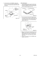
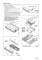
Reference Notes CAUTION 1: Locking Tabs (L-1) and (L-2) are fragile. Be careful not to break them. 1-1. Release five Locking Tabs (L-1). 1-2. Release three Locking Tabs (L-2). 1-3. Disconnect Connector (CN1231), and remove the Panel Front. 2. When reassembling, solder wire jumpers as shown in Fig. D9. 3. Before installing the Deck Assembly, be sure to place the pin of LD-SW on BOARD Main as shown in Fig. D9. Then, install the Deck Assembly while aligning the hole of Cam Gear with the pin of LDSW, the shaft of Cam Gear with the hole of LD-SW as shown in Fig. D9. 4. The DVD Mechanism & DVD Main BOARD Assembly is adjusted as a unit at factory. Therefore, do not disassemble it. Replace the DVD Mechanism & DVD Main BOARD Assembly as a unit. (S-1) [1] Cover Top (S-1) (S-5) [4] Jack Bracket [5] BOARD Front Jack Jack Plate Earth Fig. D3 (S-6) CN701 CN101 CN901 (S-6a) Mecha Plate (S-6) Earth R (S-6) (S-1) Fig. D1 * [6] DVD Mechanism & DVD Main BOARD Assembly Hook [7] Dust Cover (S-7) [3] Front Bracket (S-3) (S-3) (S-4) (L-1) (S-2) (L-1) (L-1) [2] Panel (L-2) Front CN1231 Fig. D2 *See Reference Notes 4. 1-6-2 Fig. D4 E9KGADC
-
 1
1 -
2
-
3
-
4
-
5
-
6
-
7
-
8
-
 9
9 -
 10
10 -
 11
11 -
 12
12 -
 13
13 -
 14
14 -
 15
15 -
 16
16 -
 17
17 -
 18
18 -
 19
19 -
20
-
21
-
22
-
23
-
24
-
25
-
26
-
27
-
28
-
29
-
30
-
31
-
32
-
33
-
34
-
35
-
36
-
37
-
38
-
39
-
40
-
41
-
42
-
43
-
44
-
45
-
46
-
47
-
48
-
49
-
50
-
51
-
52
-
53
-
54
-
55
-
56
-
57
-
58
-
59
-
60
-
61
-
62
-
63
-
64
-
65
-
66
-
67
-
68
-
69
-
70
-
71
-
72
-
73
-
74
-
75
-
76
-
77
-
78
-
79
-
80
-
81
-
82
-
83
-
84
-
85
-
86
-
87
 |
 |
