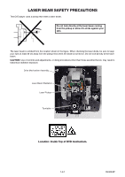
Toshiba DVR610 Service Manual - Page 8
Standard Notes For Servicing - instructions
 |
UPC - 022265001370
View all Toshiba DVR610 manuals
Add to My Manuals
Save this manual to your list of manuals |
Page 8 highlights
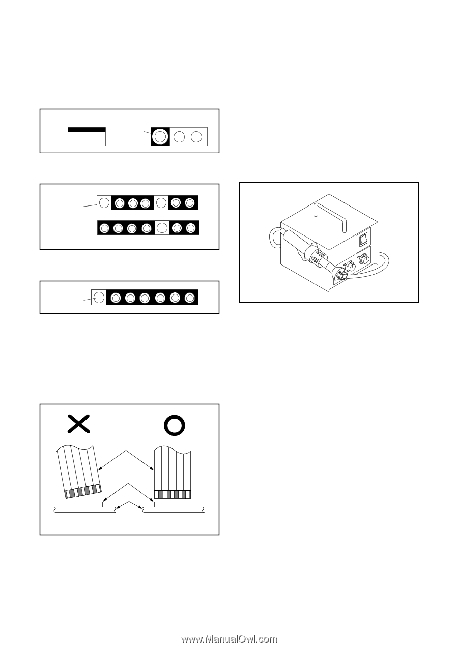
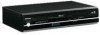
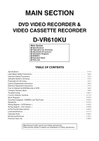
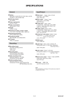
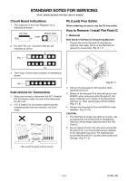
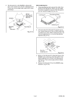
STANDARD NOTES FOR SERVICING NOTE: BOARD MEANS PRINTED CIRCUIT BOARD. Circuit Board Indications 1. The output pin of the 3 pin Regulator ICs is indicated as shown. Top View Input Out In Bottom View 2. For other ICs, pin 1 and every fifth pin are indicated as shown. 5 Pin 1 Pb (Lead) Free Solder When soldering, be sure to use the Pb free solder. How to Remove / Install Flat Pack-IC 1. Removal With Hot-Air Flat Pack-IC Desoldering Machine: 1. Prepare the hot-air flat pack-IC desoldering machine, then apply hot air to the Flat Pack-IC (about 5 to 6 seconds). (Fig. S-1-1) 10 3. The 1st pin of every male connector is indicated as shown. Pin 1 Instructions for Connectors 1. When you connect or disconnect the FFC (Flexible Foil Connector) cable, be sure to first disconnect the AC cord. 2. FFC (Flexible Foil Connector) cable should be inserted parallel into the connector, not at an angle. FFC Cable Connector BOARD Fig. S-1-1 2. Remove the flat pack-IC with tweezers while applying the hot air. 3. Bottom of the flat pack-IC is fixed with glue to the BOARD; when removing entire flat pack-IC, first apply soldering iron to center of the flat pack-IC and heat up. Then remove (glue will be melted). (Fig. S-1-6) 4. Release the flat pack-IC from the BOARD using tweezers. (Fig. S-1-6) CAUTION: 1. The Flat Pack-IC shape may differ by models. Use an appropriate hot-air flat pack-IC desoldering machine, whose shape matches that of the Flat Pack-IC. 2. Do not supply hot air to the chip parts around the flat pack-IC for over 6 seconds because damage to the chip parts may occur. Put masking tape around the flat pack-IC to protect other parts from damage. (Fig. S-1-2) * Be careful to avoid a short circuit. 1-4-1 DVDN_SN
-
 1
1 -
2
-
 3
3 -
 4
4 -
 5
5 -
 6
6 -
 7
7 -
 8
8 -
 9
9 -
 10
10 -
 11
11 -
 12
12 -
 13
13 -
14
-
15
-
16
-
17
-
18
-
19
-
20
-
21
-
22
-
23
-
24
-
25
-
26
-
27
-
28
-
29
-
30
-
31
-
32
-
33
-
34
-
35
-
36
-
37
-
38
-
39
-
40
-
41
-
42
-
43
-
44
-
45
-
46
-
47
-
48
-
49
-
50
-
51
-
52
-
53
-
54
-
55
-
56
-
57
-
58
-
59
-
60
-
61
-
62
-
63
-
64
-
65
-
66
-
67
-
68
-
69
-
70
-
71
-
72
-
73
-
74
-
75
-
76
-
77
-
78
-
79
-
80
-
81
-
82
-
83
-
84
-
85
-
86
-
87
 |
 |