Toshiba DVR610 Service Manual - Page 19
Electrical Adjustment Instructions - specs
 |
UPC - 022265001370
View all Toshiba DVR610 manuals
Add to My Manuals
Save this manual to your list of manuals |
Page 19 highlights
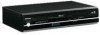
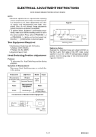
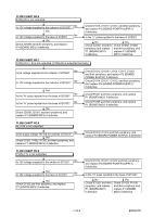
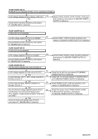
ELECTRICAL ADJUSTMENT INSTRUCTIONS NOTE: BOARD MEANS PRINTED CIRCUIT BOARD. NOTE: 1.Electrical adjustments are required after replacing circuit components and certain mechanical parts. It is important to do these adjustments only after all repairs and replacements have been completed. Also, do not attempt these adjustments unless the proper equipment is available. 2.To perform these alignment / confirmation procedures, make sure that the tracking control is set in the center position: Press either [TRACKING ] or [TRACKING ] button on the front panel first, then the [ O ] (VCR) button on the front panel. Test Equipment Required 1.Oscilloscope: Dual-trace with 10:1 probe, V-Range: 0.001~50V/Div., F-Range: DC~AC-20MHz 2.Alignment Tape (FL8A) Head Switching Position Adjustment Purpose: To determine the Head Switching position during playback. Symptom of Misadjustment: May cause Head Switching noise or vertical jitter in the picture. Figure 1 EXT. Syncronize Trigger Point CH1 CH2 1.0H 0.5H 6.5H±1H (416μs±64μs) Switching Pulse V-Sync Reference Notes: Playback the Alignment tape and adjust VR1501 so that the V-sync front edge of the CH1 video output waveform is at the 6.5H±1H (416μs±64μs) delayed position from the rising edge of the CH2 head switching pulse waveform. Test point Adj.Point Mode Input TP751(V-OUT) VR1501 TP302(RF-SW) (Switching Point) GND (BOARD MAIN) PLAY (SP) ----- Tape Measurement Equipment Spec. FL8A Oscilloscope 6.5H±1H (416μs±64μs) Connections of Measurement Equipment BOARD Main TP751 GND TP302 Oscilloscope CH1 CH2 Trig. (+) 1-7-1 E9KGAEA
-
 1
1 -
2
-
3
-
4
-
5
-
6
-
7
-
8
-
9
-
10
-
11
-
12
-
13
-
 14
14 -
 15
15 -
 16
16 -
 17
17 -
 18
18 -
 19
19 -
 20
20 -
 21
21 -
 22
22 -
 23
23 -
 24
24 -
25
-
26
-
27
-
28
-
29
-
30
-
31
-
32
-
33
-
34
-
35
-
36
-
37
-
38
-
39
-
40
-
41
-
42
-
43
-
44
-
45
-
46
-
47
-
48
-
49
-
50
-
51
-
52
-
53
-
54
-
55
-
56
-
57
-
58
-
59
-
60
-
61
-
62
-
63
-
64
-
65
-
66
-
67
-
68
-
69
-
70
-
71
-
72
-
73
-
74
-
75
-
76
-
77
-
78
-
79
-
80
-
81
-
82
-
83
-
84
-
85
-
86
-
87
 |
 |