Toshiba DVR610 Service Manual - Page 35
Flow Chart No.11
 |
UPC - 022265001370
View all Toshiba DVR610 manuals
Add to My Manuals
Save this manual to your list of manuals |
Page 35 highlights
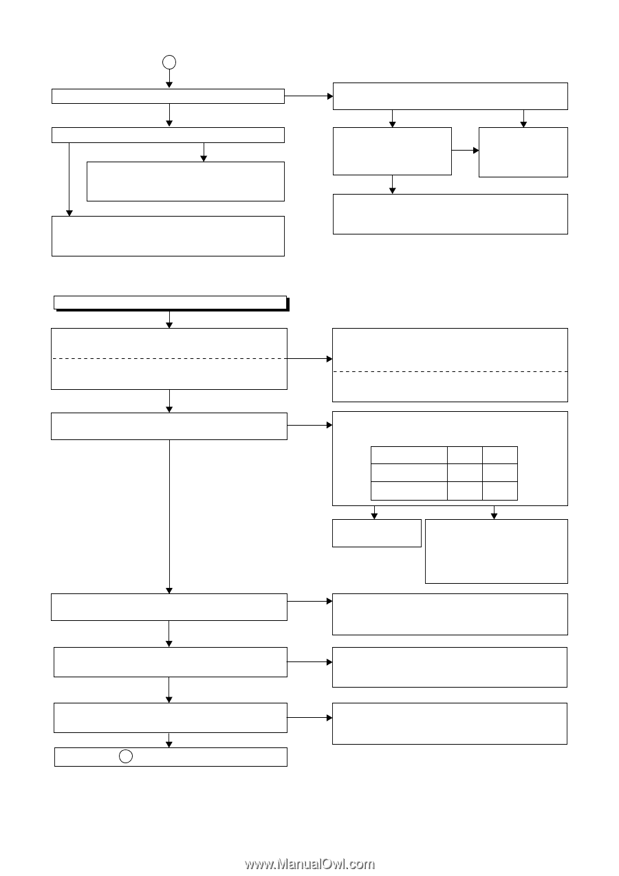
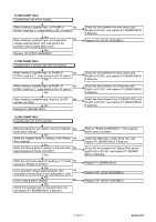
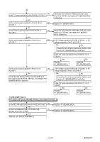
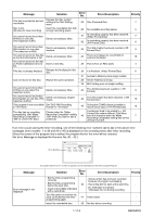
C Is the video signal outputted to Pin(15) of IC2406? No Yes Is the video signal outputted to the emitter of Q2391? Yes No Check the line between Pin(15) of IC2406 and Q2391, and replace P1 (BOARD MCV) if defective. Check the line between the emitter of Q2391 and the video output terminal (JK2751), and replace P1 (BOARD MCV) if defective. Is the "H" pulese inputted to Pin(9, 10, 11) of IC2406? Yes No Is 5V voltage supplied to Pin(16) of IC2406? Yes Is -5V voltage supplied to Pin(7) of IC2406? No Replace P1 (BOARD MCV) or P3 (BOARD POWER SUPPLY). Check the AL+5V, AL-5V line and replace P1 (BOARD MCV) or P3 (BOARD POWER SUPPLY) if defective. FLOW CHART NO.11 Hi-Fi E-E audio does not operate normally. Are the audio signals inputted to each pin of IC2801? No IC2801 4,11PIN AUDIO-IN1 (REAR) IC2801 5,14PIN AUDIO-IN2 (FRONT) Yes Are the audio signals outputted to Pin(3,13) of No IC2801? Yes No Are the audio signals inputted to Pin(7,69) of IC1451? Yes Is the 5V voltage supplied to Pin(5, 15, 32, 36, 46) of No IC1451, or the 9V voltage supplied to Pin(3) of IC1451? Yes Is the serial data and the clock signal supplied to No Pin(37, 38) of IC1451? Yes Continued to D on the next page. Check the line between audio input terminal and each pin of IC2801, and replace P1 (BOARD MCV) if defective. IC2801 4,11PIN → JK2804 AUDIO-IN1 (REAR) IC2801 5,14PIN → JK1232, JK1233 AUDIO-IN2 (FRONT) Are active level of Pin(9,10) of IC2801 become as shown below? INPUT LINE(REAR) LINE(FRONT) 9PIN 10PIN H H L H Yes Replace P1 (BOARD MCV). No Check the line between Pin(9,10) of IC2801 and Pin(60,61) of IC1501, and replace P1 (BOARD MCV) if defective. Check the line between Pin(3,13) of IC2801 and Pin(7,69) of IC1451, and replace P1 (BOARD MCV) if defective. Check the circuit of AL+5V, P-ON+5V(2) and P-ON+9V, and replace P1 (BOARD MCV) or P3 (BOARD POWER SUPPLY) if defective. Check the line between Pin(37, 38) of IC1451 and Pin(17,18) of IC1501, and replace P1 (BOARD MCV) if defective. 1-10-14 E9KGATR
-
 1
1 -
2
-
3
-
4
-
5
-
6
-
7
-
8
-
9
-
10
-
11
-
12
-
13
-
14
-
15
-
16
-
17
-
18
-
19
-
20
-
21
-
22
-
23
-
24
-
25
-
26
-
27
-
28
-
29
-
 30
30 -
 31
31 -
 32
32 -
 33
33 -
 34
34 -
 35
35 -
 36
36 -
 37
37 -
 38
38 -
 39
39 -
 40
40 -
41
-
42
-
43
-
44
-
45
-
46
-
47
-
48
-
49
-
50
-
51
-
52
-
53
-
54
-
55
-
56
-
57
-
58
-
59
-
60
-
61
-
62
-
63
-
64
-
65
-
66
-
67
-
68
-
69
-
70
-
71
-
72
-
73
-
74
-
75
-
76
-
77
-
78
-
79
-
80
-
81
-
82
-
83
-
84
-
85
-
86
-
87
 |
 |