Toshiba DVR610 Service Manual - Page 9
Fig. S-1-2, Fig. S-1-3, Fig. S-1-4
 |
UPC - 022265001370
View all Toshiba DVR610 manuals
Add to My Manuals
Save this manual to your list of manuals |
Page 9 highlights
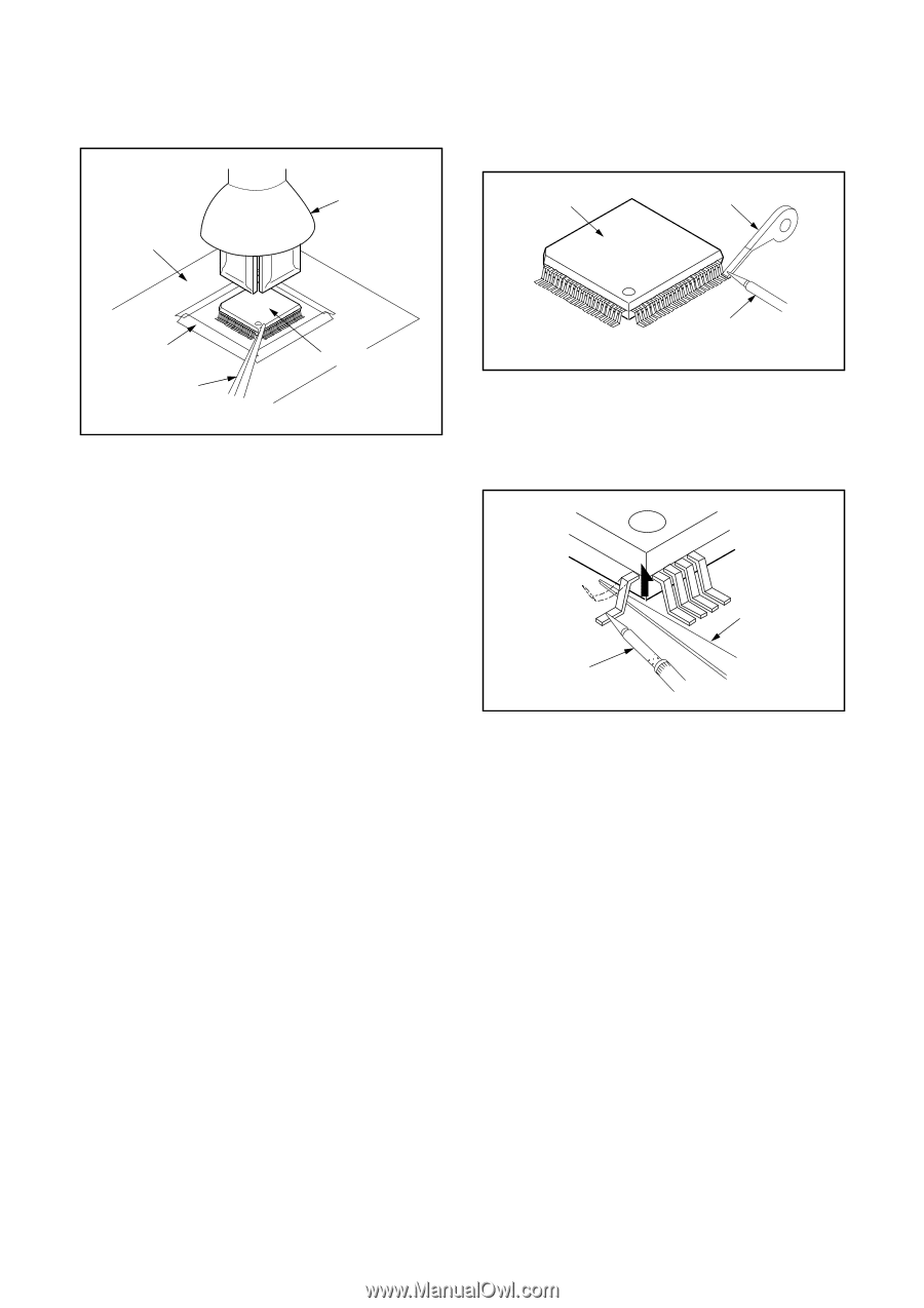
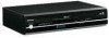
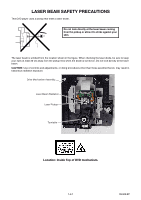
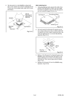
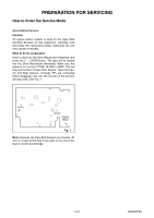
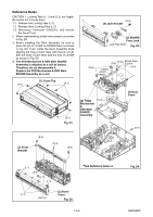
3. The flat pack-IC on the BOARD is affixed with glue, so be careful not to break or damage the foil of each pin or the solder lands under the IC when removing it. BOARD Hot-air Flat Pack-IC Desoldering Machine With Soldering Iron: 1. Using desoldering braid, remove the solder from all pins of the flat pack-IC. When you use solder flux which is applied to all pins of the flat pack-IC, you can remove it easily. (Fig. S-1-3) Flat Pack-IC Desoldering Braid Masking Tape Tweezers Flat Pack-IC Fig. S-1-2 Soldering Iron Fig. S-1-3 2. Lift each lead of the flat pack-IC upward one by one, using a sharp pin or wire to which solder will not adhere (iron wire). When heating the pins, use a fine tip soldering iron or a hot air desoldering machine. (Fig. S-1-4) Sharp Pin Fine Tip Soldering Iron Fig. S-1-4 3. Bottom of the flat pack-IC is fixed with glue to the BOARD; when removing entire flat pack-IC, first apply soldering iron to center of the flat pack-IC and heat up. Then remove (glue will be melted). (Fig. S-1-6) 4. Release the flat pack-IC from the BOARD using tweezers. (Fig. S-1-6) 1-4-2 DVDN_SN
-
 1
1 -
2
-
3
-
 4
4 -
 5
5 -
 6
6 -
 7
7 -
 8
8 -
 9
9 -
 10
10 -
 11
11 -
 12
12 -
 13
13 -
 14
14 -
15
-
16
-
17
-
18
-
19
-
20
-
21
-
22
-
23
-
24
-
25
-
26
-
27
-
28
-
29
-
30
-
31
-
32
-
33
-
34
-
35
-
36
-
37
-
38
-
39
-
40
-
41
-
42
-
43
-
44
-
45
-
46
-
47
-
48
-
49
-
50
-
51
-
52
-
53
-
54
-
55
-
56
-
57
-
58
-
59
-
60
-
61
-
62
-
63
-
64
-
65
-
66
-
67
-
68
-
69
-
70
-
71
-
72
-
73
-
74
-
75
-
76
-
77
-
78
-
79
-
80
-
81
-
82
-
83
-
84
-
85
-
86
-
87
 |
 |