Toshiba DVR610 Service Manual - Page 50
Power Supply Block Diagram
 |
UPC - 022265001370
View all Toshiba DVR610 manuals
Add to My Manuals
Save this manual to your list of manuals |
Page 50 highlights
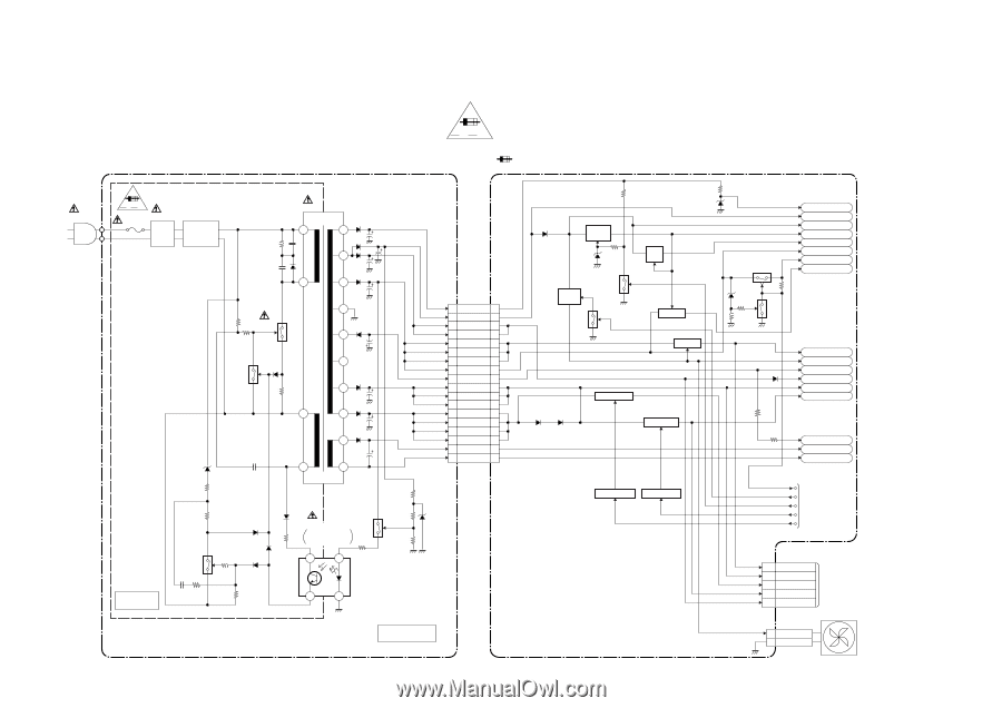
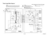
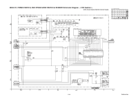
Power Supply Block Diagram CAUTION ! Fixed voltage (or Auto voltage selectable) power supply circuit is used in this unit. If Main Fuse (F1001) is blown , check to see that all components in the power supply circuit are not defective before you connect the AC plug to the AC power supply. Otherwise it may cause some components in the power supply circuit to fail. AC1001 HOT CIRCUIT. BE CAREFUL. F A V F1001 L1001 1A 250V LINE FILTER D1001 - D1004 BRIDGE RECTIFIER Q1001 Q1003 T1001 2 20 19 4 18 17 16 15 14 8 13 12 7 11 F A V NOTE: BOARD MEANS PRINTED CIRCUIT BOARD. CAUTION ! For continued protection against fire hazard, replace only with the same type fuse. ATTENTION : Pour une protection continue les risqes d'Incele n'utiliser que des fusible de même type. Risk of fire-replace fuse as marked. "This symbol means fast operating fuse." "Ce symbole reprèsente un fusible à fusion rapide." NOTE: The voltage for parts in hot circuit is measured using hot GND as a common terminal. CN1607 CN1101 1 AL+44V 1 2 AL+12V(1) 2 3 AL+12V(2) 3 4 AL+12V(2) 4 5 DVD+5V 5 6 DVD+5V 6 7 DVD+5V 7 8 AL+5V 8 17 AL-30V 17 18 AL+2.8V 18 19 AL+2.8V 19 20 AL+2.8V 20 25 AL+4V 25 26 AL+4V 26 27 AL+4V 27 28 AL+4V 28 29 F1 29 30 F2 30 Q1055 SW +9V Q1052 SW Q1102 +11V Q1103 Q1057 SW +5V SW+5V Q1056 Q1101 SW+5V +3.3V REG. IC2503 IC2504 +1.8V REG. Q1104 Q1105 AL+18V AL+12V EV+11V P-ON+9V P-ON+5V AL+5V TIMER+5V P-ON+5V P-ON+5V P-ON+11V AL-30V EV+10.5V EV+2.8V P-ON+1.8V -FL F1 F2 IC1010 ERROR Q1031 VOLTAGE DET Q2206 Q2205 SWITCHING SWITCHING P-DOWN-H PWR-SW P-ON-L REG-CONT1 REG-CONT2 TO SYSTEM CONTROL BLOCK DIAGRAM Q1008 HOT 4 1 3 2 BOARD POWER SUPPLY COLD BOARD MAIN CN2204 20-22 P-ON+5V 10-12 EV+2.8V 15-17 P-ON+3.3V 6,7 P-ON+1.8V 25-27 EV+10.5V CN1102 1 FAN 2 GND TO DVD MAIN BOARD (CN101) FAN 1-12-10 E9KGABLP
-
 1
1 -
2
-
3
-
4
-
5
-
6
-
7
-
8
-
9
-
10
-
11
-
12
-
13
-
14
-
15
-
16
-
17
-
18
-
19
-
20
-
21
-
22
-
23
-
24
-
25
-
26
-
27
-
28
-
29
-
30
-
31
-
32
-
33
-
34
-
35
-
36
-
37
-
38
-
39
-
40
-
41
-
42
-
43
-
44
-
 45
45 -
 46
46 -
 47
47 -
 48
48 -
 49
49 -
 50
50 -
 51
51 -
 52
52 -
 53
53 -
 54
54 -
 55
55 -
56
-
57
-
58
-
59
-
60
-
61
-
62
-
63
-
64
-
65
-
66
-
67
-
68
-
69
-
70
-
71
-
72
-
73
-
74
-
75
-
76
-
77
-
78
-
79
-
80
-
81
-
82
-
83
-
84
-
85
-
86
-
87
 |
 |