Toshiba DVR610 Service Manual - Page 13
Cabinet Disassembly Instructions - dvd vcr
 |
UPC - 022265001370
View all Toshiba DVR610 manuals
Add to My Manuals
Save this manual to your list of manuals |
Page 13 highlights
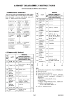
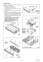
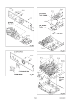
CABINET DISASSEMBLY INSTRUCTIONS NOTE: BOARD MEANS PRINTED CIRCUIT BOARD. 1. Disassembly Flowchart This flowchart indicates the disassembly steps to gain access to item(s) to be serviced. When reassembling, follow the steps in reverse order. Bend, route, and dress the cables as they were originally. [1] Cover Top [20] Front Bracket R [2] Panel Front [3] Front Bracket [4] Jack Bracket [5] BOARD Front Jack [10] Motor DC Fan [9] Fan Holder [6] DVD Mechanism & DVD Main BOARD Assembly [7] Dust Cover [12] BOARD Power Supply [11] Panel Rear [8] Panel Rear Unit [13] BOARD Holder [15] Deck Assembly [16] BOARD Power Switch [17] BOARD DVD open /close Switch [14] VCR Chassis Unit [18] BOARD Main [19] Deck Pedestal 2. Disassembly Method ID/ LOC. No. PART REMOVAL Fig. No. REMOVE/*UNHOOK/ UNLOCK/RELEASE/ UNPLUG/DESOLDER Note [1] Cover Top D1 7(S-1) --- 1 [2] Panel Front D2 (S-2), *5(L-1), *3(L-2), 1-1 *CN1231 1-2 1-3 [3] Front Bracket D2 2(S-3), (S-4) --- [4] Jack Bracket D3 (S-5) --- [5] BOARD Front Jack D3 Jack Plate Earth --- DVD Mechanism 4(S-6), (S-6a), (S-7), [6] & DVD Main D4 *CN101, *CN701, *CN901, Mecha Plate 4 BOARD Earth R Assembly [7] Dust Cover D4 ---------- --- [8] Panel Rear Unit D5 3(S-8), 6(S-9), *CN1102 --- ID/ LOC. No. PART REMOVAL Fig. No. REMOVE/*UNHOOK/ UNLOCK/RELEASE/ UNPLUG/DESOLDER Note [9] Fan Holder D6 3(S-10) --- [10] Motor DC Fan D6 ---------- --- [11] Panel Rear D6 ---------- --- BOARD [12] Power D7 4(S-11), *CN1101 --- Supply [13] BOARD Holder D7 4(S-12), Plate Earth --- VCR [14] Chassis Unit 5(S-13), 4(S-14), D8 (S-15), (S-16), (S-17), --- (S-18), Board Washer [15] Deck Assembly D9 (S-19), (S-20), Desolder 2 3 BOARD [16] Power D9 Desolder --- Switch BOARD [17] DVD open/ close D9 Desolder --- Switch [18] BOARD Main D9 ---------- --- [19] Deck Pedestal D10 7(S-21) --- [20] Front Bracket R 2(S-22), (S-23) D10 DV Plate Earth, DV Jack --- ↓ ↓ ↓ ↓ ↓ (1) (2) (3) (4) (5) Note: (1): Identification (location) No. of parts in the figures (2): Name of the part (3): Figure Number for reference (4): Identification of parts to be removed, unhooked, unlocked, released, unplugged, unclamped, or desoldered. P=Spring, L=Locking Tab, S=Screw, CN=Connector *=Unhook, Unlock, Release, Unplug, or Desolder e.g. 6(S-1) = six Screws (S-1), 5(L-1) = five Locking Tabs (L-1) (5): Refer to "Reference Notes." 1-6-1 E9KGADC
-
 1
1 -
2
-
3
-
4
-
5
-
6
-
7
-
 8
8 -
 9
9 -
 10
10 -
 11
11 -
 12
12 -
 13
13 -
 14
14 -
 15
15 -
 16
16 -
 17
17 -
 18
18 -
19
-
20
-
21
-
22
-
23
-
24
-
25
-
26
-
27
-
28
-
29
-
30
-
31
-
32
-
33
-
34
-
35
-
36
-
37
-
38
-
39
-
40
-
41
-
42
-
43
-
44
-
45
-
46
-
47
-
48
-
49
-
50
-
51
-
52
-
53
-
54
-
55
-
56
-
57
-
58
-
59
-
60
-
61
-
62
-
63
-
64
-
65
-
66
-
67
-
68
-
69
-
70
-
71
-
72
-
73
-
74
-
75
-
76
-
77
-
78
-
79
-
80
-
81
-
82
-
83
-
84
-
85
-
86
-
87
 |
 |
