Yamaha DME32 DME32 Owners Manual - Page 19
Connecting the Power Cord, Turning On & Off the DME32
 |
View all Yamaha DME32 manuals
Add to My Manuals
Save this manual to your list of manuals |
Page 19 highlights
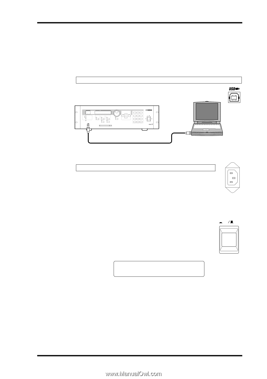
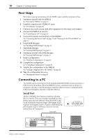
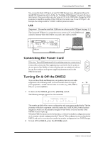
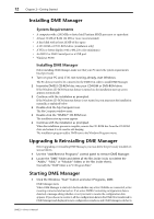
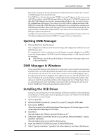
Connecting the Power Cord 11 You can specify which COM port on your PC DME Manager uses, although you'll need to install DME Manager in order to do this. See "Installing DME Manager" on page 12 for more information. Using a text editor, open the "setup.ini" file in the DME folder. Change the COM parameter to match the number of the COM port you want to use. To use COM port 2, for example, the setting should be "COM2" (without quotation marks). USB Important: You need to install the USB driver in order to use the USB port. See page 13. The front panel USB port is a convenient way to connect a PC to the DME32 and is ideal for systems where the DME32 rear panel is not easily accessible. SCENE NO. 88 48kHz 44.1kHz LOCK EMERGENCY CONFIGURATION SCENE XXXXXYAMAHAXDME32 XDigitalXMixingXEngine COMPONENT PARAMETER VALUE PROTECT UTILITY CARD DATA USER DEFINE INC DEC SCENE RECALL 7 8 9 4 5 6 1 2 3 STORE 0 RECALL POWER ON OFF DIGITAL MIXING ENGINE USB port USB cable USB port Connecting the Power Cord AC IN Warning: Turn off all equipment before making any power connections. Connect the socket-end of the supplied power cord to the AC IN socket on the rear panel of the DME32. Connect the plug-end to a suitable AC wall outlet, one that conforms to the power supply requirements stated on the DME32 rear panel. Turning On & Off the DME32 To prevent loud clicks and thumps in your speakers, turn on your audio equipment in the following order (reverse this order when turning off your equipment)-sound sources, mixer or recorder (e.g., 02R, DME32, D24, etc.), power amplifiers. POWER ON OFF 1 To turn on the DME32, press the [POWER] switch. The following message appears for a few moments. XXXXXYAMAHAXDME32 XDigitalXMixingXEngine The number and title of the current configuration and scene appear on the display. The first parameter of the first component is selected, unless the [USER DEFINE] button has been assigned, in which case, the parameter assigned to that button is selected and the USER DEFINE indicator lights up. When the DME32 is turned on for the first time, or when it's initialized, configuration memory A contains a simple configuration titled "Mtrx16." This configuration is stored inside the DME32 and can be overwritten by transferring another configuration from DME Manager. 2 To turn off the DME32, press the [POWER] switch. DME32-Owner's Manual
-
 1
1 -
2
-
3
-
4
-
5
-
6
-
7
-
8
-
9
-
10
-
11
-
12
-
13
-
 14
14 -
 15
15 -
 16
16 -
 17
17 -
 18
18 -
 19
19 -
 20
20 -
 21
21 -
 22
22 -
 23
23 -
 24
24 -
25
-
26
-
27
-
28
-
29
-
30
-
31
-
32
-
33
-
34
-
35
-
36
-
37
-
38
-
39
-
40
-
41
-
42
-
43
-
44
-
45
-
46
-
47
-
48
-
49
-
50
-
51
-
52
-
53
-
54
-
55
-
56
-
57
-
58
-
59
-
60
-
61
-
62
-
63
-
64
-
65
-
66
-
67
-
68
-
69
-
70
-
71
-
72
-
73
-
74
-
75
-
76
-
77
-
78
-
79
-
80
-
81
-
82
-
83
-
84
-
85
-
86
-
87
-
88
-
89
-
90
-
91
-
92
-
93
-
94
-
95
-
96
-
97
-
98
-
99
-
100
-
101
-
102
-
103
-
104
-
105
-
106
-
107
-
108
-
109
-
110
-
111
-
112
-
113
-
114
-
115
-
116
-
117
-
118
-
119
-
120
-
121
-
122
-
123
-
124
-
125
-
126
-
127
-
128
-
129
-
130
-
131
-
132
-
133
-
134
-
135
-
136
-
137
-
138
-
139
-
140
-
141
-
142
-
143
-
144
-
145
-
146
-
147
-
148
-
149
-
150
-
151
-
152
-
153
-
154
-
155
-
156
-
157
-
158
-
159
-
160
-
161
-
162
-
163
-
164
-
165
-
166
-
167
-
168
-
169
-
170
-
171
-
172
-
173
-
174
-
175
-
176
-
177
-
178
-
179
-
180
-
181
-
182
-
183
-
184
-
185
-
186
-
187
-
188
-
189
-
190
-
191
-
192
-
193
-
194
-
195
-
196
-
197
-
198
-
199
-
200
-
201
-
202
-
203
-
204
-
205
-
206
-
207
-
208
-
209
-
210
-
211
-
212
-
213
-
214
-
215
-
216
-
217
-
218
-
219
-
220
-
221
-
222
-
223
-
224
-
225
-
226
-
227
-
228
-
229
-
230
-
231
-
232
-
233
-
234
-
235
-
236
-
237
-
238
-
239
-
240
-
241
-
242
-
243
-
244
-
245
-
246
-
247
-
248
-
249
-
250
-
251
-
252
-
253
-
254
-
255
-
256
-
257
-
258
-
259
-
260
-
261
-
262
-
263
-
264
-
265
-
266
-
267
-
268
-
269
-
270
-
271
-
272
-
273
-
274
-
275
-
276
-
277
-
278
-
279
-
280
-
281
-
282
-
283
-
284
-
285
-
286
-
287
-
288
-
289
-
290
-
291
-
292
-
293
-
294
-
295
-
296
 |
 |