Yamaha DME32 DME32 Owners Manual - Page 217
About the GPI Interface, GPI Connectors
 |
View all Yamaha DME32 manuals
Add to My Manuals
Save this manual to your list of manuals |
Page 217 highlights
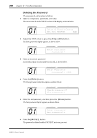
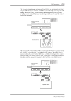
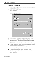
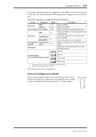
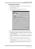
212 Chapter 11-GPI Interface About the GPI Interface The GPI (General Purpose Interface) allows remote interaction between DME32 functions and custom-made controllers and other equipment. The DME32 features 16 GPI inputs and 16 GPI outputs. GPI inputs can be used to recall scenes and configurations or adjust component parameters. They can also be configured for use with Emergency mode, in which the DME32 mutes all outputs. The DME32 can be configured to switch a GPI output when a GPI input is triggered, or to transmit a Program Change message when a scene or configuration is recalled via a GPI input, or to transmit a Control Change message when a component parameter is adjusted via a GPI input. GPI outputs can be used to trigger other equipment when scenes are recalled or component parameters are adjusted from DME Manager, front panel controls, GPI inputs, or by using MIDI Program Changes and Control Changes. GPI outputs can be configured so that they switch between high and low when a parameter is adjusted above or below a specified threshold. In a multiple-unit system, all GPI interfaces can be used, providing a maximum of 64 GPI inputs and 64 GPI outputs with four DME32s. GPI Connectors The GPI connectors are 16-pin Euro-block sockets, which mate with 16-pin Euro-block plugs. 16 15 14 13 12 11 10 9 IN +V The top connector contains the IN terminals for GPI inputs 9 16 15 14 13 12 11 10 9 OUT GND through 16 and +V terminals. The second connector contains the OUT terminals for GPI out- 8 7 6 5 4 3 2 1 puts 9 through 16 and GND IN +V terminals. The third connector contains 8 7 6 5 4 3 2 1 the IN terminals for GPI inputs OUT GND 1 through 8 and +V terminals. The bottom connector contains the OUT terminals for GPI outputs 1 through 8 and GND terminals. The open terminal voltage of each +V terminal is 15 V and the maximum supply current available from each terminal is 6 mA. External controllers and other equipment can easily be attached to the GPI interface by using Euro-block plugs. Simply insert the bare wire into the relevant hole and tighten the adjacent screw. To prevent interference, use shielded cable and attach the shield to a GND terminal. DME32-Owner's Manual
-
 1
1 -
2
-
3
-
4
-
5
-
6
-
7
-
8
-
9
-
10
-
11
-
12
-
13
-
14
-
15
-
16
-
17
-
18
-
19
-
20
-
21
-
22
-
23
-
24
-
25
-
26
-
27
-
28
-
29
-
30
-
31
-
32
-
33
-
34
-
35
-
36
-
37
-
38
-
39
-
40
-
41
-
42
-
43
-
44
-
45
-
46
-
47
-
48
-
49
-
50
-
51
-
52
-
53
-
54
-
55
-
56
-
57
-
58
-
59
-
60
-
61
-
62
-
63
-
64
-
65
-
66
-
67
-
68
-
69
-
70
-
71
-
72
-
73
-
74
-
75
-
76
-
77
-
78
-
79
-
80
-
81
-
82
-
83
-
84
-
85
-
86
-
87
-
88
-
89
-
90
-
91
-
92
-
93
-
94
-
95
-
96
-
97
-
98
-
99
-
100
-
101
-
102
-
103
-
104
-
105
-
106
-
107
-
108
-
109
-
110
-
111
-
112
-
113
-
114
-
115
-
116
-
117
-
118
-
119
-
120
-
121
-
122
-
123
-
124
-
125
-
126
-
127
-
128
-
129
-
130
-
131
-
132
-
133
-
134
-
135
-
136
-
137
-
138
-
139
-
140
-
141
-
142
-
143
-
144
-
145
-
146
-
147
-
148
-
149
-
150
-
151
-
152
-
153
-
154
-
155
-
156
-
157
-
158
-
159
-
160
-
161
-
162
-
163
-
164
-
165
-
166
-
167
-
168
-
169
-
170
-
171
-
172
-
173
-
174
-
175
-
176
-
177
-
178
-
179
-
180
-
181
-
182
-
183
-
184
-
185
-
186
-
187
-
188
-
189
-
190
-
191
-
192
-
193
-
194
-
195
-
196
-
197
-
198
-
199
-
200
-
201
-
202
-
203
-
204
-
205
-
206
-
207
-
208
-
209
-
210
-
211
-
 212
212 -
 213
213 -
 214
214 -
 215
215 -
 216
216 -
 217
217 -
 218
218 -
 219
219 -
 220
220 -
 221
221 -
 222
222 -
223
-
224
-
225
-
226
-
227
-
228
-
229
-
230
-
231
-
232
-
233
-
234
-
235
-
236
-
237
-
238
-
239
-
240
-
241
-
242
-
243
-
244
-
245
-
246
-
247
-
248
-
249
-
250
-
251
-
252
-
253
-
254
-
255
-
256
-
257
-
258
-
259
-
260
-
261
-
262
-
263
-
264
-
265
-
266
-
267
-
268
-
269
-
270
-
271
-
272
-
273
-
274
-
275
-
276
-
277
-
278
-
279
-
280
-
281
-
282
-
283
-
284
-
285
-
286
-
287
-
288
-
289
-
290
-
291
-
292
-
293
-
294
-
295
-
296
 |
 |
