Yamaha DVD-S1800 Owner's Manual - Page 11
Rear panel, Remote control connectors and RS-232C terminal
 |
View all Yamaha DVD-S1800 manuals
Add to My Manuals
Save this manual to your list of manuals |
Page 11 highlights
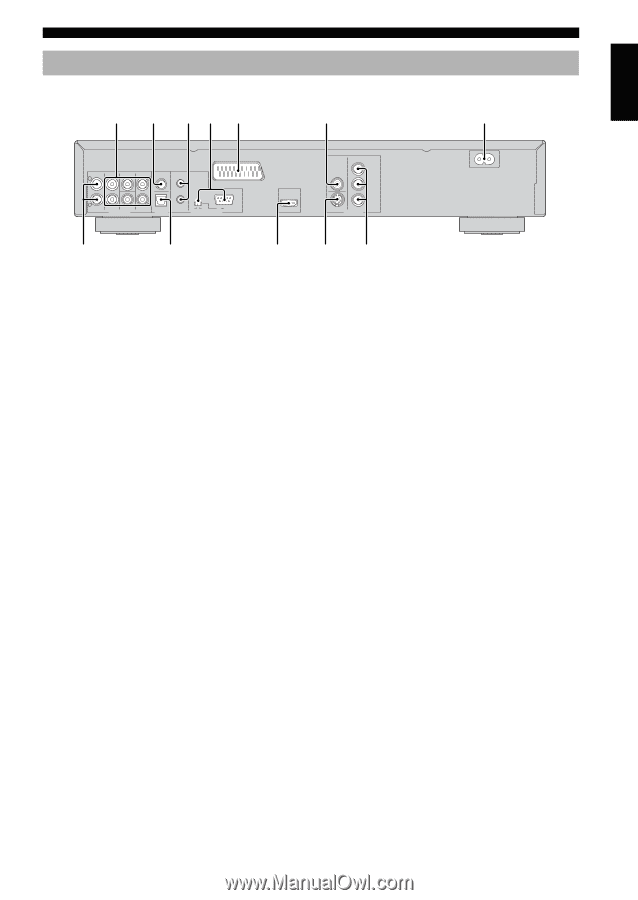
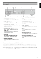
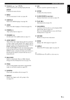
English Rear panel FUNCTIONAL OVERVIEW 1 2 34 5 6 7 CENTER COAXIAL IN L L AV R R MIXED 2CH FRONT SUBWOOFER SURROUND AUDIO OUT OPTICAL DIGITAL OUT ON OFF RS 232C REMOTE CONTROL HDMI VIDEO PR / CR PB / CB Y S VIDEO COMPONENT VIDEO OUT MAINS 8 9 0 q w (U.K., Europe, and Russia models) 1 AUDIO OUT (6ch discrete) jacks Connect to the 6ch input jacks of your AV receiver. 7 MAINS Connect the supplied power cable. 2 DIGITAL (COAXIAL) jack Connect to the coaxial input jack of your AV receiver. 3 REMOTE CONTROL (IN/OUT) connectors Use in custom installations to transmit remote control signals via cable connections. 8 AUDIO OUT (MIXED 2CH) jacks Connect to the audio input jacks of your AV receiver or stereo system. 9 DIGITAL (OPTICAL) jack Connect to the optical input jack of your AV receiver. 4 REMOTE CONTROL (RS-232C) terminal (U.S.A., Canada, U.K., Europe, and Russia models only) Use as an expansion terminal for commercial use. Consult your dealer for details. 5 AV terminal (U.K., Europe, and Russia models only) Connect to SCART input terminal of your TV. 6 VIDEO OUT (VIDEO) jack Connect to the composite video input jack of your AV receiver. 0 HDMI jack Connect to the HDMI input jack of your HDMI component. q VIDEO OUT (S VIDEO) jack Connect to the S-video input jack of your AV receiver. w VIDEO OUT (COMPONENT) jacks Connect to the component input jacks of your AV receiver. ■ Remote control connectors and RS-232C terminal The REMOTE CONTROL (IN/OUT) connectors and the REMOTE CONTROL (RS-232C) terminal are used in custom installation. Keep the RS-232C switch set to OFF and do not connect any cables to these connectors during normal use. Caution: Do not touch the inner pins of the jacks on the rear panel of this unit. Electrostatic discharge may cause permanent damage to this unit. 7 En
-
 1
1 -
2
-
3
-
4
-
5
-
 6
6 -
 7
7 -
 8
8 -
 9
9 -
 10
10 -
 11
11 -
 12
12 -
 13
13 -
 14
14 -
 15
15 -
 16
16 -
17
-
18
-
19
-
20
-
21
-
22
-
23
-
24
-
25
-
26
-
27
-
28
-
29
-
30
-
31
-
32
-
33
-
34
-
35
-
36
-
37
-
38
-
39
-
40
-
41
-
42
-
43
-
44
-
45
-
46
-
47
-
48
-
49
 |
 |