Yamaha MG166CX-USB Owner's Manual - Page 17
LINE Input Jacks stereo channels, Equalizer HIGH, MID and LOW - 16 usb
 |
View all Yamaha MG166CX-USB manuals
Add to My Manuals
Save this manual to your list of manuals |
Page 17 highlights
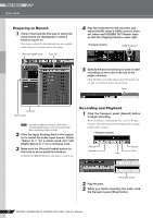
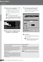
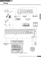
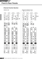
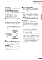
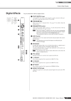
Reference Front & Rear Panels 1 MIC Input jacks These are balanced XLR-type microphone input jacks. (1: Ground; 2: Hot; 3: Cold) 2 LINE Input Jacks (monaural channels) These are balanced TRS phone-jack line inputs. (T: Hot; R: Cold; S: Ground). You can connect either balanced or unbalanced phone plugs to these jacks. 3 LINE Input Jacks (stereo channels) These are unbalanced phone-jack stereo line inputs. 4 LINE Input Jacks (stereo channels) These are unbalanced stereo RCA pin jacks. NOTE On channels that provide multiple input jack options only one type of jack can be used at a time. 5 INSERT Jacks These jacks can be used to insert an external signal-processing device between the equalizer and fader of the corresponding monaural input channel. The INSERT jacks are ideal for connecting devices such as graphic equalizers, compressors, or noise filters into the corresponding channels. NOTE These are TRS (tip, ring, sleeve) phone jacks that carry both the send and return signal (tip = send/out; ring = return/in; sleeve = ground). Patching external devices via an INSERT jack requires a special cable such as illustrated below (insert cable sold separately). To the input jack of the external processor To the INSERT I/O jack Tip: OUT Sleeve (Ground) Ring: IN Tip: OUT Tip: IN To the output jack of the external processor CAUTION The signal output from the INSERT jacks is reverse-phased. This should not be a problem when connecting to an effect unit, but please be aware of the possibility of phase conflict when connecting to other types of device. A reversedphased signal may result in degraded sound quality or even complete sound cancellation. 6 GAIN Control Adjusts the input signal level. To get the best balance between the S/N ratio and the dynamic range, adjust the gain so that the PEAK indicator 9 lights only occasionally and briefly on the highest input transients. The -60 to -16 scale is the MIC input adjustment range. The -34 to +10 scale is the LINE input adjustment range. 7 Switch (High-Pass Filter) This switch toggles the HPF on or off. To turn the HPF on, press the switch in ( ). The HPF cuts frequencies below 80 Hz (the HPF does not apply to the line inputs of stereo input channels 3, 4). 8 COMP Control Adjusts the amount of compression applied to the channel. As the knob is turned to the right the compression ratio increases while the output gain is automatically adjusted accordingly. The result is smoother, more even dynamics because louder signals are attenuated while the overall level is boosted. NOTE Avoid setting the compression too high, as the higher average output level that results may lead to feedback. 9 PEAK indicator The peak level of the post-EQ signal is detected, and the PEAK indicator lights red when the level reaches 3 dB below clipping. For XLR-equipped stereo input channels, both the post-EQ and post-mic-amp peak levels are detected, and the indicator lights red if either of these levels reaches 3 dB below clipping. 0 Equalizer (HIGH, MID and LOW) This three-band equalizer adjusts the channel's high, mid, and low frequency bands. Setting the knob to the "▼" position produces a flat response in the corresponding band. Turning the knob to the right boosts the corresponding frequency band, while turning to the left attenuates the band. The monaural channels have MID frequency controls to adjust the midrange frequency band. The following table shows the EQ type, frequency, and maximum cut/boost for each of the three bands. Band HIGH MID LOW Type Shelving Peaking Shelving Frequency 10 kHz 2.5 kHz* 100 Hz Maximum Cut/Boost ±15 dB * The monaural channel MID frequency can be adjusted from 250 Hz to 5 kHz. The MID frequency is 2.5 kHz when the MID frequency control is set at the center position. MG206C-USB/MG166CX-USB/MG166C-USB Owner's Manual 17
-
 1
1 -
2
-
3
-
4
-
5
-
6
-
7
-
8
-
9
-
10
-
11
-
 12
12 -
 13
13 -
 14
14 -
 15
15 -
 16
16 -
 17
17 -
 18
18 -
 19
19 -
 20
20 -
 21
21 -
 22
22 -
23
-
24
-
25
-
26
-
27
-
28
-
29
-
30
-
31
-
32
-
33
-
34
-
35
-
36
-
37
 |
 |