Yamaha MG166CX-USB Owner's Manual - Page 19
Digital Effects, FOOT SWITCH Jack, PROGRAM Dial, PARAMETER Control, AUX Control, ON Switch - stereo mixer with effects
 |
View all Yamaha MG166CX-USB manuals
Add to My Manuals
Save this manual to your list of manuals |
Page 19 highlights
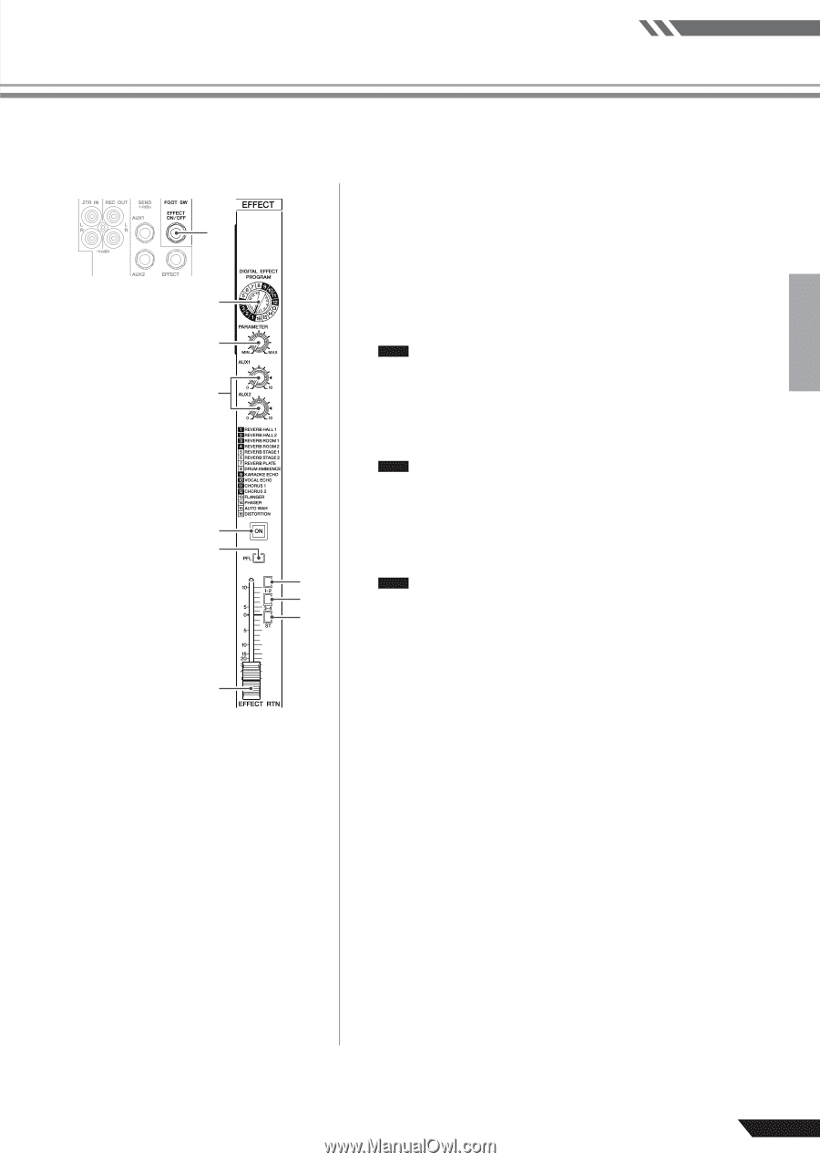
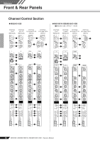
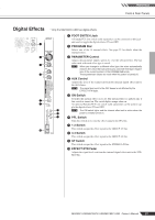
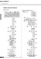
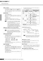
Reference Front & Rear Panels Digital Effects 1 2 3 4 5 6 0 * Only the MG166CX-USB has digital effects. 1 FOOT SWITCH Jack A Yamaha FC5 foot switch (sold separately) can be connected to this jack and used to toggle the digital effects ON and OFF. 2 PROGRAM Dial Selects one of the 16 internal effects. See page 23 for details about the internal effects. 3 PARAMETER Control Adjusts the parameter (depth, speed, etc.) for the selected effect. The last value used with each effect type is saved. NOTE When you change to a different effect type, the mixer automatically restores the value that was previously used with that type (regardless of the current position of the PARAMETER knob). These parameter values are reset when the power is turned off. 4 AUX Control Adjusts the level of the signal sent from the internal digital effect unit to the AUX buses. NOTE The signal level sent to the AUX buses is not affected by the EFFECT RTN fader. 5 ON Switch Switches the internal effect on or off. The internal effect is applied only if this switch is turned on. The switch lights orange when on. An optional Yamaha FC5 foot switch (sold separately) can be used to toggle the digital effects ON and OFF. 7 NOTE The ON switch lights and the internal effect unit is active when the 8 power is initially turned on. 9 6 PFL Switch Turn this switch on to send the effect signal to the PFL bus. 7 1-2 Switch This switch assigns the effect signal to the GROUP 1/2 bus. 8 3-4 Switch This switch assigns the effect signal to the GROUP 3/4 bus. 9 ST Switch This switch assigns the effect signal to the STEREO L/R bus. 0 EFFECT RTN Fader Adjusts the signal level sent from the internal digital effect unit to the STEREO bus. MG206C-USB/MG166CX-USB/MG166C-USB Owner's Manual 19
-
 1
1 -
2
-
3
-
4
-
5
-
6
-
7
-
8
-
9
-
10
-
11
-
12
-
13
-
 14
14 -
 15
15 -
 16
16 -
 17
17 -
 18
18 -
 19
19 -
 20
20 -
 21
21 -
 22
22 -
 23
23 -
 24
24 -
25
-
26
-
27
-
28
-
29
-
30
-
31
-
32
-
33
-
34
-
35
-
36
-
37
 |
 |