Yamaha MG166CX-USB Owner's Manual - Page 21
Rec Out L, R Jacks, Return L Mono - drives
 |
View all Yamaha MG166CX-USB manuals
Add to My Manuals
Save this manual to your list of manuals |
Page 21 highlights
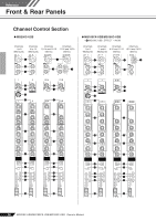
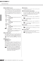
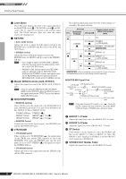
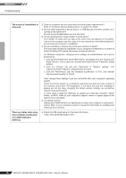
Reference Front & Rear Panels 1 USB Connector Connects to the computer via the included cable. The USB connector outputs the same signal as the REC OUT jacks. When connecting or disconnecting the USB cable be sure to turn the 2TR IN/USB control all CAUTION the way down. 2 SEND Jacks (AUX, EFFECT) These impedance balanced* TRS phone jacks output the signals from the AUX/EFFECT buses. The pre-fader send option should be selected if you are connecting to a monitor system, while the post-fader send option is the best choice when connecting to external signal processors (e.g. effects units). See "AUX, EFFECT Control" on page 18 for information on the types of signals sent by the AUX and EFFECT controls on each mixer model. 3 GROUP OUT (1 to 4) Jacks These impedance-balanced* TRS phone jacks output the GROUP 1/2 and 3/4 signals. Use these jacks to connect to the input jacks of an multi-track recorder, external mixer, or other such device. 4 REC OUT (L, R) Jacks These RCA pin jacks can be connected to an external recorder such as an MD recorder in order to record the same signal that is being output via the STEREO OUT jacks. NOTE The mixer's STEREO OUT Master fader has no affect on the signal output via these jacks. Be sure to make appropriate level adjustments at the recording device. 5 2TR IN Jacks These RCA pin jacks input a stereo sound source. Use these jacks when you want to connect a CD player directly to the mixer. NOTE • Select where you want to send the signal using the 2TR IN/USB switch, and adjust the signal level using the 2TR IN/USB control in the Master Control section. • If signals are input via both the 2TR IN jacks and the USB connector, the signals are mixed. 6 RETURN L (MONO), R Jacks These are unbalanced phone-jack type line inputs. The signal received by these jacks can be sent to the STEREO L/R bus as well as the AUX1 and AUX2 buses. When a stereo signal is returned a mono mix of the signal is sent to the AUX1 and AUX2 buses. These jacks are typically used to receive the signal returned from an external effect device (reverb, delay, etc.). NOTE • These jacks can also be used as an auxiliary stereo input. • If you connect to the L (MONO) jack only, the mixer will recognize the signal as monaural and will send the identical signal to both the L and R jacks. 7 STEREO OUT (L, R) Jacks These jacks deliver the mixer's stereo output. You use these jacks, for example, to connect to the power amplifier driving your main speakers. You can also connect these jacks to a recording device when you wish to record mixer's stereo output while using the STEREO OUT Master fader J for level control. • XLR jacks XLR-type balanced output jacks. • LINE jacks TRS phone-type balanced output jacks. 8 MONITOR OUT jacks These are impedance-balanced* TRS phone-type output jacks. NOTE The signal output by these jacks is determined by the MONITOR switch, the 2TR IN/USB switch, and the PFL switches on the input channels. 9 PHONES Jack Connect a pair of headphones to this TRS phone-type output jack. The PHONES jack outputs the same signal as the MONITOR OUT jacks. 0 PHANTOM +48 V Switch This switch toggles phantom power on and off. When the switch is on the mixer supplies +48V phantom power to all channels that have XLR mic input jacks. Turn this switch on when using one or more phantom-powered condenser microphones. NOTE When this switch is on the mixer supplies DC +48 V power to pins 2 and 3 of all XLR-type MIC INPUT jacks. • Be sure to leave this switch off if you do not need phantom power. CAUTION • When turning the switch on, be sure that only condenser microphones are connected to the XLR input jacks. Devices other than condenser mics may be damaged if connected to the phantom power supply. Note, however, that the switch may be left on when connecting to balanced dynamic microphones. • To prevent damage to speakers, be sure to turn off power amplifiers (or powered speakers) before turning this switch on or off. We also recommend that you turn all output controls (STEREO OUT Master fader, GROUP 1-2 fader, GROUP 3-4 fader, etc.) to their minimum settings before operating the switch to avoid the risk of loud noises that could cause hearing loss or device damage. A POWER Indicator This indicator lights when the mixer's power is ON. * impedance balanced Since the hot and cold terminals of impedance balanced output jacks have the same impedance, these output jacks are less affected by induced noise. MG206C-USB/MG166CX-USB/MG166C-USB Owner's Manual 21
-
 1
1 -
2
-
3
-
4
-
5
-
6
-
7
-
8
-
9
-
10
-
11
-
12
-
13
-
14
-
15
-
 16
16 -
 17
17 -
 18
18 -
 19
19 -
 20
20 -
 21
21 -
 22
22 -
 23
23 -
 24
24 -
 25
25 -
 26
26 -
27
-
28
-
29
-
30
-
31
-
32
-
33
-
34
-
35
-
36
-
37
 |
 |