Yamaha MGP32X Owner's Manual - Page 11
Channel control block, Mono input - mixer 32 channel
 |
View all Yamaha MGP32X manuals
Add to My Manuals
Save this manual to your list of manuals |
Page 11 highlights
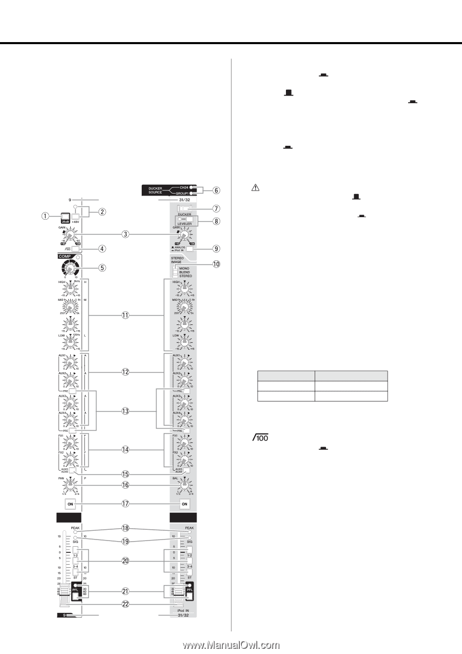
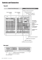
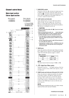
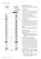
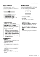
Controls and Connectors Channel control block Mono input section Stereo input section Mono channels 1-24 (MGP32X) 1-16 (MGP24X) Stereo channels 25-32 (MGP32X) 17-24 (MGP24X) * y-!0 are for CH29/ 30, CH31/32 {CH21/ 22,CH23/24} only. Channel number q 26dB (PAD) switch Turning this switch on ( ) attenuates the input signal from the INPUT jack of the mono channel by 26dB. Turn this switch off ( ) if you have connected a microphone or other device with a low input level to the channel. Turn it on ( ) if you have connected a line-level device. w +48V switch and indicator Toggles phantom power on and off. When this switch is turned on ( ), the mixer supplies DC +48V power to INPUT A of XLR input jacks. Turn this switch on when using one or more phantom-powered condenser microphones. The indicator is on when the switch is on. CAUTION • Be sure to leave this switch off ( phantom power. ) if you do not need • When turning phantom power on ( ), follow the important precautions below, in order to prevent noise and possible damage to the mixer and external devices. • Turn this switch off when connecting a device that does not support phantom power to INPUT A of XLR input jacks • Do not connect/disconnect a cable to/from channels 124 {1-16} while this switch on. • Turn the mixer's output controls - STEREO master and GROUP faders- all the way down when turning phantom power on/off. e GAIN knob Adjusts the sensitivity of the input signal. Monaural channels have a 26dB switch (q) that lets you change the range of this control. The adjustable sensitivity range is as follows. Mono channel 26dB switch ON OFF Range -34dB to +10dB -60dB to -16dB NOTE The stereo channel is fixed to a range of -34dB to +10dB. r (High Pass Filter) switch Turning this switch on ( ) will apply a high-pass filter that attenuates frequencies below 100Hz in the signal by a slope of 12dB/octave. t COMP knobs and indicator (Channel 9-24 {9-16}) Adjusts the amount of compression applied to the channel. As the knob is turned to the right the compression ratio increases while the output gain is automatically adjusted accordingly. The result is smoother, more even dynamics because louder signals are attenuated while the overall level is boosted. The COMP indicator comes on when the compressor operates. NOTE Avoid setting the compression too high, as the higher average output level that results may lead to feedback. Channel number Continue to next page MGP32X/MGP24X Owner's Manual 11
-
 1
1 -
2
-
3
-
4
-
5
-
 6
6 -
 7
7 -
 8
8 -
 9
9 -
 10
10 -
 11
11 -
 12
12 -
 13
13 -
 14
14 -
 15
15 -
 16
16 -
17
-
18
-
19
-
20
-
21
-
22
-
23
-
24
-
25
-
26
-
27
-
28
-
29
-
30
-
31
-
32
-
33
-
34
-
35
-
36
-
37
-
38
-
39
-
40
-
41
-
42
-
43
-
44
-
45
-
46
-
47
-
48
-
49
-
50
-
51
-
52
-
53
-
54
-
55
-
56
 |
 |