Yamaha MGP32X Owner's Manual - Page 45
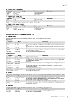
COMP/DUCKER/LEVELER Parameter List, Type=Comp, Type=MulitiBand
 |
View all Yamaha MGP32X manuals
Add to My Manuals
Save this manual to your list of manuals |
Page 45 highlights
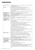
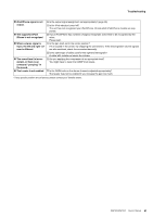
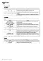
FX2 SPX (14: SYMPHONIC) Parameter Range Frequency 0.00 - 39.7 Hz Depth 0 - 127 Delay 0.0 - 50.0 ms FX2 SPX (15: DOUBLER) Parameter Depth Range Type Range 0 - 32 0 - 12 Sound4 - Sound1, Normal, Rythm1 - Rythm4 FX2 SPX (16: RADIO VOICE) Parameter Range Cutoff 0 - 127 Drive 0 - 127 LPF 1.0 kHz - 18.0 kHz, Thru Modulation frequency Modulation depth Delay offset Pitch shift depth Pitch range Effect type Filter cutoff Distortion drive level LPF frequency Description Description Description Appendix COMP/DUCKER/LEVELER Parameter List COMPRESSOR If a signal higher than a specified threshold level is input, the output level is adjusted by a specified ratio. Type=Comp Parameter Threshold Ratio Attack Release Out Level Range -48 to -6 dB 1.0 - 20.0 1 - 40 ms 10 - 680 ms -12 to +12 dB Description This determines the level of input signal required to trigger the compressor. This determines the amount of compression. A larger value results in a stronger compression effect. This determines how soon the signal will be compressed once the compressor has been triggered. This determines how soon the compressor returns to its normal gain once the trigger signal level drops below the threshold. This sets the compressor's output signal level. Type=MulitiBand Parameter L-M Xover M-H Xover Release Out Level L(/M/H)-Thresh Range 21.2 Hz - 4.0 kHz 42.5 Hz - 8.0 kHz 10 - 3000 ms -12 to +12 dB -54 to -6 dB L(/M/H)-Ratio 1.0 - 20.0 L(/M/H)-Attack 1 - 200 ms L(/M/H)-Gain -INF, -36 to +18 dB L(/M/H)-Bypass ON, OFF Description Low/mid crossover frequency Mid/high crossover frequency This determines how soon the compressor returns to its normal gain once the trigger signal level drops below the threshold. Output level This determines the level of input signal required to trigger the low/mid/high band compressor. This determines the amount of low/mid/high band compression. A larger value results in a stronger compression effect. Low/mid/high band compressor attack Low/mid/high band compressor gain Low/mid/high band bypass on/off DUCKER If the selected input source signal level exceeds the specified threshold level, the output level is attenuated by a specified amount (range). Parameter Source Threshold Range Release Range CH24 {CH16}, GROUP1 -60 to 0 dB -70 to 0 dB 1 ms - 50 s Description This determines whether the ducker source signal is channel 24 {16} or GROUP1. This determines the level of trigger signal required to active the ducker. If the source input signal exceeds this level, the ducker begins to be applied. This determines the amount of attenuation when the ducker is activated. This determines how soon the ducker returns to its normal gain once the trigger signal level drops below the threshold. LEVELER If a signal higher than a specified threshold level is input, the output level is adjusted to the specified level. Parameter Threshold Out Gain Range -60 to 0 dB -20 to +40 dB Description This determines the level of input signal required to trigger the leveler. This sets leveler's output signal level. MGP32X/MGP24X Owner's Manual 45
-
 1
1 -
2
-
3
-
4
-
5
-
6
-
7
-
8
-
9
-
10
-
11
-
12
-
13
-
14
-
15
-
16
-
17
-
18
-
19
-
20
-
21
-
22
-
23
-
24
-
25
-
26
-
27
-
28
-
29
-
30
-
31
-
32
-
33
-
34
-
35
-
36
-
37
-
38
-
39
-
 40
40 -
 41
41 -
 42
42 -
 43
43 -
 44
44 -
 45
45 -
 46
46 -
 47
47 -
 48
48 -
 49
49 -
 50
50 -
51
-
52
-
53
-
54
-
55
-
56
 |
 |
