Yamaha MGP32X Owner's Manual - Page 37
Using Other Functions, Applying the Low Pass Filter (LPF), Using the Ducker function
 |
View all Yamaha MGP32X manuals
Add to My Manuals
Save this manual to your list of manuals |
Page 37 highlights
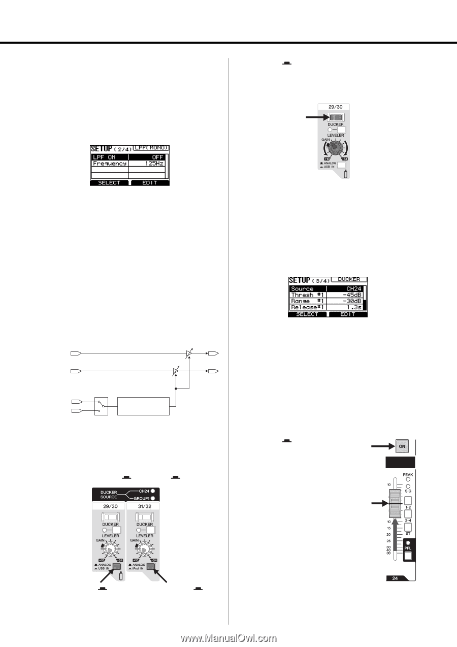
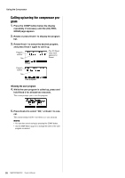
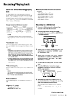
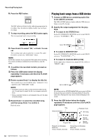
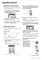
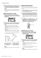
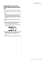
Using Other Functions Applying the Low Pass Filter (LPF) A Low Pass Filter (LPF) can be applied to the signal output from the STEREO bus L/R to the MONO OUT connector. LPF is commonly used for subwoofer applications. 1. Press the SETUP button below the display repeatedly if necessary until the SETUP (2/4) LPF (MONO) page appears. 2. Turn on ( ) the DUCKER switch of the chan- nel to which the device is connected in step 1, and then rotate the GAIN knob to adjust the input level of the channel. Turn on Level adjustment 2. Rotate Knob 1 to select "LPF ON," and then rotate Knob 2 to set it to "ON." The LPF indicator next to the MONO master fader comes on 3. Rotate Knob 1 to select "Frequency," and then rotate Knob 2 to set the frequency. Using the Ducker function The Ducker function automatically lowers the level of background music to accommodate the voice of an announcer coming in on another channel. Ducker signal flow CH29/30 (CH21/22) CH31/32 (CH23/24) CH24 (CH16) GROUP1 DUCKER SOURCE Volume detection Volume control 1. Connect a music player or device for playing background music. Connect the device to CH29/30 or CH31/32 {CH21/22 or CH23/24}. To connect the USB device or iPod/iPhone, set the input select switch to USB IN ( ) or iPod IN ( ) respectively. 3. Connect a microphone to the input source channel. For the MGP32X unit connect the microphone to CH24 and for the MGP24X unit connect the microphone to CH16, or assign the source channel to GROUP OUT 1. 4. Press the SETUP button below the display repeatedly if necessary until the (3/4) DUCKER page appears. 5. Confirm that "Source" is selected, and then rotate Knob 2 to set the input source to "CH24 {CH16}" or "GROUP1." If you automatically control the volume of background music via an independent microphone input, it is recommended that you set the input source to CH24 {CH16}. If you want to control the volume of background music via multiple microphones inputs, you should set the input source to "GROUP1." 6. Adjust the input of the microphone to an appropriate level. 7. Turn on ( ) the ON switch of the channel to which the microphone is connected in step 3, and then raise the channel fader to around "0" (nominal). Turn on "0" Set to USB IN ( ) Set to iPod IN ( ) Continue to next page MGP32X/MGP24X Owner's Manual 37
-
 1
1 -
2
-
3
-
4
-
5
-
6
-
7
-
8
-
9
-
10
-
11
-
12
-
13
-
14
-
15
-
16
-
17
-
18
-
19
-
20
-
21
-
22
-
23
-
24
-
25
-
26
-
27
-
28
-
29
-
30
-
31
-
 32
32 -
 33
33 -
 34
34 -
 35
35 -
 36
36 -
 37
37 -
 38
38 -
 39
39 -
 40
40 -
 41
41 -
 42
42 -
43
-
44
-
45
-
46
-
47
-
48
-
49
-
50
-
51
-
52
-
53
-
54
-
55
-
56
 |
 |