Yamaha MGP32X Owner's Manual - Page 20
TALKBACK GROUP ST Stereo switch
 |
View all Yamaha MGP32X manuals
Add to My Manuals
Save this manual to your list of manuals |
Page 20 highlights
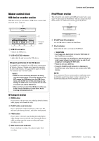
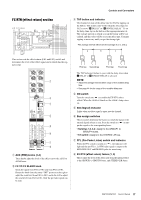
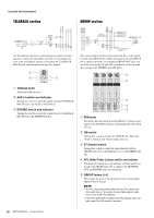
Controls and Connectors TALKBACK section GROUP section Use the talkback function to send instructions mainly from the operator to musicians and studio staff. This section adjusts the level of the microphone signal received from the TALKBACK MIC IN jack, and determines the bus to be output. This section adjusts the level and controls the flow of the signals from the four GROUP buses. While the signal from each GROUP bus is always sent to the corresponding GROUP OUT jack, you are also free to use the ST and AFL switches to selectively send these groups to the STEREO and AFL buses. q Talkback knob Adjusts the talkback level. w AUX1-4 switch and indicator Turning this switch on sends the signal from the TALKBACK MIC IN jack to the AUX1 to AUX4 buses. e STEREO switch and indicator Turning this switch on sends the signal from the TALKBACK MIC IN jack to the STEREO L/R bus. q PAN knob Determines how the signal from the GROUP 1-4 buses is positioned on the STEREO L/R buses when turning the ON switch (w) on. w ON switch Turning this switch on enables the GROUP fader. When the switch is turned on, the switch's lamp comes on. e ST (Stereo) switch Turning this switch on sends the signal adjusted with the GROUP fader (t) via the PAN knob (q) to the STEREO L/R bus. r AFL (After-Fader Listen) switch and indictor When the AFL switch is on, the indicator will light and the signal after the GROUP fader (t) is output to the MONITOR OUT and PHONES jacks for monitoring. t GROUP faders (1-4) These adjust the level of the signal sent to the corresponding GROUP OUT 1-4 jacks. NOTE • The PFL signal has priority when both the PFL switch and AFL switch are on. To monitor the post-fader signal, make sure to turn off all PFL switches. • If the PFL (preferred) is enabled, the AFL indicator does not light, even if the AFL switch is pressed. 20 MGP32X/MGP24X Owner's Manual
-
 1
1 -
2
-
3
-
4
-
5
-
6
-
7
-
8
-
9
-
10
-
11
-
12
-
13
-
14
-
 15
15 -
 16
16 -
 17
17 -
 18
18 -
 19
19 -
 20
20 -
 21
21 -
 22
22 -
 23
23 -
 24
24 -
 25
25 -
26
-
27
-
28
-
29
-
30
-
31
-
32
-
33
-
34
-
35
-
36
-
37
-
38
-
39
-
40
-
41
-
42
-
43
-
44
-
45
-
46
-
47
-
48
-
49
-
50
-
51
-
52
-
53
-
54
-
55
-
56
 |
 |
