Yamaha QY700 Owner's Manual - Page 50
Variation mode = System
 |
View all Yamaha QY700 manuals
Add to My Manuals
Save this manual to your list of manuals |
Page 50 highlights
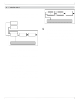
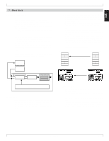
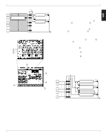
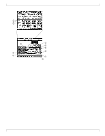
Effect blocks diagram in Song mode (Variation mode= INS) 2 3 1 1 Reverb effect 2 Variation effect 8 Chorus effect 16 17 64 75 32 Voice mode (mixer) 2 3 1 4 6 8 5 Effect mode (Effect Connection) 7 BASIC CONCEPTS Variation mode = System • When Variation mode is set to System, the three effects will 1 be connected as shown in the diagram below. • The signals from all tone generator parts will be sent to the reverb effect, chorus effect, and variation effect according to the Voice mode settings Reverb Send Level 1, Chorus Send Level 2, and Variation Send Level 3. Here you can adjust the effect depth for each part. • The overall depth of each effect can be adjusted by the Effect mode settings Reverb Return Level 4, Chorus Return Level 5, and Variation Return Level 6. Here you can set the amount of the signal that is returned from each effect, to adjust the overall depth of the effect. • The stereo location of the effect output is determined by the Effect mode settings Reverb Pan 7, Chorus Pan 8, and Variation Pan 9. • If Variation Mode = System, three bus lines will be connected. Send Chorus To Reverb 0 is a bus line that connects the Chorus Effect to the Reverb Effect. Send Variation To Chorus A is a bus line that connects the Variation Effect to the Chorus Effect. Send Variation To Reverb B is a bus line that connects the Variation Effect to the Reverb Effect. By using these three bus lines, you can use the effects in a variety of ways, such as connecting the three effects in series, or dividing them. Effect blocks diagram in Song mode (Variation mode = SYS) 1 2 3 1 Reverb effect 2 0 Chorus effect 16 A 17 B Variation effect 32 74 85 96 Chapter 1 49
-
 1
1 -
2
-
3
-
4
-
5
-
6
-
7
-
8
-
9
-
10
-
11
-
12
-
13
-
14
-
15
-
16
-
17
-
18
-
19
-
20
-
21
-
22
-
23
-
24
-
25
-
26
-
27
-
28
-
29
-
30
-
31
-
32
-
33
-
34
-
35
-
36
-
37
-
38
-
39
-
40
-
41
-
42
-
43
-
44
-
 45
45 -
 46
46 -
 47
47 -
 48
48 -
 49
49 -
 50
50 -
 51
51 -
 52
52 -
 53
53 -
 54
54 -
 55
55 -
56
-
57
-
58
-
59
-
60
-
61
-
62
-
63
-
64
-
65
-
66
-
67
-
68
-
69
-
70
-
71
-
72
-
73
-
74
-
75
-
76
-
77
-
78
-
79
-
80
-
81
-
82
-
83
-
84
-
85
-
86
-
87
-
88
-
89
-
90
-
91
-
92
-
93
-
94
-
95
-
96
-
97
-
98
-
99
-
100
-
101
-
102
-
103
-
104
-
105
-
106
-
107
-
108
-
109
-
110
-
111
-
112
-
113
-
114
-
115
-
116
-
117
-
118
-
119
-
120
-
121
-
122
-
123
-
124
-
125
-
126
-
127
-
128
-
129
-
130
-
131
-
132
-
133
-
134
-
135
-
136
-
137
-
138
-
139
-
140
-
141
-
142
-
143
-
144
-
145
-
146
-
147
-
148
-
149
-
150
-
151
-
152
-
153
-
154
-
155
-
156
-
157
-
158
-
159
-
160
-
161
-
162
-
163
-
164
-
165
-
166
-
167
-
168
-
169
-
170
-
171
-
172
-
173
-
174
-
175
-
176
-
177
-
178
-
179
-
180
-
181
-
182
-
183
-
184
-
185
-
186
-
187
-
188
-
189
-
190
-
191
-
192
-
193
-
194
-
195
-
196
-
197
-
198
-
199
-
200
-
201
-
202
-
203
-
204
-
205
-
206
-
207
-
208
-
209
-
210
-
211
-
212
-
213
-
214
-
215
-
216
-
217
-
218
-
219
-
220
-
221
-
222
-
223
-
224
-
225
-
226
-
227
-
228
-
229
-
230
-
231
-
232
-
233
-
234
-
235
-
236
-
237
-
238
-
239
-
240
-
241
-
242
-
243
-
244
-
245
-
246
-
247
-
248
-
249
-
250
-
251
-
252
-
253
-
254
-
255
-
256
-
257
-
258
-
259
-
260
-
261
-
262
-
263
-
264
-
265
-
266
-
267
-
268
-
269
-
270
-
271
-
272
-
273
-
274
-
275
-
276
-
277
-
278
-
279
-
280
-
281
-
282
-
283
-
284
-
285
-
286
-
287
-
288
-
289
-
290
-
291
-
292
-
293
-
294
-
295
-
296
-
297
-
298
-
299
-
300
-
301
-
302
-
303
-
304
-
305
-
306
-
307
-
308
-
309
-
310
-
311
-
312
-
313
-
314
-
315
-
316
-
317
-
318
-
319
-
320
-
321
-
322
-
323
-
324
-
325
-
326
-
327
-
328
-
329
-
330
-
331
-
332
-
333
-
334
 |
 |
