Yamaha RX-V683 RX-V683 Owner s Manual - Page 34
Connecting the FM/AM antennas, Assembling and connecting the AM antenna
 |
View all Yamaha RX-V683 manuals
Add to My Manuals
Save this manual to your list of manuals |
Page 34 highlights
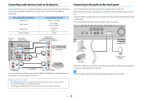
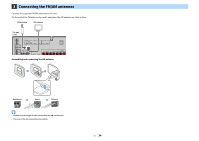
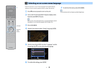
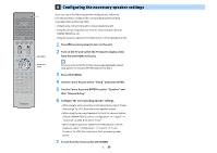
3 Connecting the FM/AM antennas Connect the supplied FM/AM antennas to the unit. Fix the end of the FM antenna to a wall, and place the AM antenna on a flat surface. FM antenna AM antenna The unit (rear) TRIGGER OUT 12V 0.1A IN OUT REMOTE AUDIO 1 (2 TV) OPTICAL AUDIO 2 OPTICAL AUDIO 3 COAXIAL HDMI OUT (HDCP2.2) ARC HDMI (HDCP2.2) 1 2 3 (1 BD/DVD) ANTENNA (4 RADIO) FM AM AV 1 COMPONENT VIDEO AV 2 VIDEO HDMI 4 5 SURROUND COAXIAL Y PB PR ZONE OUT PRE OUT CENTER NETWORK (3 NET) SPEAKERS FRONT EXTRA SP2 SURROUND BACK / ZONE2 / BI-AMP SINGLE Assembling and connecting the AM antenna Hold down Insert Release X • Unwind only the length of cable needed from the AM antenna unit. • The wires of the AM antenna have no polarity. En 34
-
 1
1 -
2
-
3
-
4
-
5
-
6
-
7
-
8
-
9
-
10
-
11
-
12
-
13
-
14
-
15
-
16
-
17
-
18
-
19
-
20
-
21
-
22
-
23
-
24
-
25
-
26
-
27
-
28
-
 29
29 -
 30
30 -
 31
31 -
 32
32 -
 33
33 -
 34
34 -
 35
35 -
 36
36 -
 37
37 -
 38
38 -
 39
39 -
40
-
41
-
42
-
43
-
44
-
45
-
46
-
47
-
48
-
49
-
50
-
51
-
52
-
53
-
54
-
55
-
56
-
57
-
58
-
59
-
60
-
61
-
62
-
63
-
64
-
65
-
66
-
67
-
68
-
69
-
70
-
71
-
72
-
73
-
74
-
75
-
76
-
77
-
78
-
79
-
80
-
81
-
82
-
83
-
84
-
85
-
86
-
87
-
88
-
89
-
90
-
91
-
92
-
93
-
94
-
95
-
96
-
97
-
98
-
99
-
100
-
101
-
102
-
103
-
104
-
105
-
106
-
107
-
108
-
109
-
110
-
111
-
112
-
113
-
114
-
115
-
116
-
117
-
118
-
119
-
120
-
121
-
122
-
123
-
124
-
125
-
126
-
127
-
128
-
129
-
130
-
131
-
132
-
133
-
134
-
135
-
136
-
137
-
138
-
139
-
140
-
141
-
142
-
143
-
144
-
145
-
146
-
147
-
148
-
149
-
150
-
151
-
152
 |
 |

En
34
3
Connecting the FM/AM antennas
Connect the supplied FM/AM antennas to the unit.
Fix the end of the FM antenna to a wall, and place the AM antenna on a flat surface.
Assembling and connecting the AM antenna
X
•
Unwind only the length of cable needed from the AM antenna unit.
•
The wires of the AM antenna have no polarity.
OPTICAL
OPTICAL
COAXIAL
COAXIAL
AUDIO
1
AUDIO
2
AUDIO
3
AV 1
AV 2
(2
TV)
P
B
Y
P
R
(
1
BD
/DVD)
HDMI
(
HDCP2.2
)
5
4
3
2
1
HDMI
(
HDCP2.2
)
ARC
ANTENNA
FM
AM
SURROUND
CENTER
FRONT
SINGLE
SURROUND BACK
/
ZONE
2
/
BI-AMP
SPEAKERS
VIDEO
ZONE OUT
PRE
OUT
NETWORK
REMOTE
(3 NET)
IN
OUT
TRIGGER OUT
12V
0.1A
EXTRA SP
2
COMPONENT VIDEO
HDMI
OUT
(
4
RADIO)
AM antenna
FM antenna
The unit
(rear)
Hold down
Insert
Release