Audiovox VE1510DV User Manual - Page 10
I00-200VAC
 |
UPC - 044476004940
View all Audiovox VE1510DV manuals
Add to My Manuals
Save this manual to your list of manuals |
Page 10 highlights
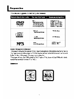
ll Interconnect Diagram SoLAKE:t iL; FMANT SPEAKER (R) • a V aim • • • TNUT • a. tiNtdso Cobb • ea* Ir 1.ii- I00-200VAC INPUT OC 12V,SA OuUluI AV-Terralmioutput Pad SuPPIRO (LCDUnderVet) dACtiIENr • ReversingPut connector, of the loft andright speakers will rosjllin the spea•er balancebeing reversed. • Prior to making connectionson tne unil remove to AC power cord from the power source 9
-
 1
1 -
2
-
3
-
4
-
 5
5 -
 6
6 -
 7
7 -
 8
8 -
 9
9 -
 10
10 -
 11
11 -
 12
12 -
 13
13 -
 14
14 -
 15
15 -
16
-
17
-
18
-
19
-
20
-
21
-
22
-
23
-
24
-
25
-
26
-
27
-
28
-
29
-
30
-
31
-
32
-
33
-
34
-
35
-
36
-
37
-
38
-
39
-
40
-
41
-
42
-
43
-
44
-
45
-
46
-
47
-
48
-
49
-
50
-
51
-
52
-
53
-
54
-
55
-
56
-
57
-
58
-
59
-
60
 |
 |

ll
Interconnect
Diagram
SoLAKE:t
iL;
SPEAKER
(R)
FM
ANT
aim
tiNtdso
Cobb
•
a
V
•
•
TNUT
•
a.
•
•
ea*
AV-Terralmi
output
Pad
SuPPIRO
(LCD
Under
Vet)
AC
IN
I
r
1.ii—
dtiEr
I00-200VAC
INPUT
OC 12V,SA
Ou
Ulu
I
•
Reversing
Put
connector,
of
the loft
and
right speakers
will
rosjll
in
the
spea•er
balance
being reversed.
•
Prior
to
making
connections
on
tne
unil
remove
to
AC
power cord
from
the
power
source
9