Bose Lifestyle 10 Owner's guide - Page 14
&velment
 |
View all Bose Lifestyle 10 manuals
Add to My Manuals
Save this manual to your list of manuals |
Page 14 highlights
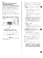
SERIAL DATA OUTPUT& A B CAUTIOI EE THE 130TTOM ATTENTI N-VOIRENFOND ZONE I Z ONE 2 r TAPE C10 VIDEO D Cirs) r11 )UTPUT INPU r 0 7 For 220-240V Models The Connections Tohear music asit was intended,always takecare toinsert the left connector into the left jack (white to white). and the right connectorinto theright jack (red tored).(Reversal will dono harm, butwillreversethesoundstage.) Complete theconnections totherear panelof theLifestyle music center (see Fig.7), with theMusic Center's ACpower cord unplugged. t SERIAL DATA OUTPUT: Insert black connectorof the long coaxial cable leading from the ACoustimast powered speaker system. Note: These identicaljacks are used with the Acoustimass poweredspeaker systemandotherauxiliary equipment 2. ZONE 1: Insert the connectors of the long coaxial cable suppliedwith yourAcoustimasspowered speaker system.(Alternatively.Zone 1may beconnected toanother Bose" Lifestyle speaker model. See the "Zones -A New Concept' section.) 3. ZONE 2:Insert theconnectorsof thelong coaxial cablessupplied with theLifestyle powered speaker system. Note: Thebogcoaxiallinecablessuppliedwithpowered Bosesystemscanyaudbsigngs from theMusicCenteno thebuilt-inpowerarnplifier. 4. TAPEOUT: Insert connectorsof the cable from theinputs of anexternaltape deckinorder torecord from the Lifestylemusic center. 5. TAPEPLAY:Insert connectors of thecablefrom the outputs ofanexternal tape deck (or otherlinelevel component) for playback using the Music Centers • tape mode. 6. VIDEO SOUND:Insert connectorsof the cable from theaudiooutputs ofanexternalcomponent, suchasa stereoTV,VCR,or videodisc (CD-Video)player. (See the 'UsingExternalComponents" section.) 7. AUX: Insert the connectorsola cable from theoutputsof anyadditionalexternalcomponent,suchas amulti-disc CD changer, asecond tapeplayer,or anyotherlinelevel source. 8. FM ANTENNA:Insert theconnectorfrom theoutdoor antennaorhouse antenna system(seeFig.8). Note: l youuseanindoorantenna,selecta 75ohmantenna. Formaximum reception. installindoorFMantennasashighas passible, withtheirannsfullyextended. &velment withorientation torthebestperformance.Receptionwillgenerally improve whenthearmsofthe 'rareperpendiculartoa lineof sight to theradiotransmitter.Infringeareas, anexternalantenna willusuallyimprovereceptionsignificantly, regardless of the geographiclocation. To install an antenna, please consult your dealer or experiencedantennaexpert.Follow allsafety instructions. 13
-
 1
1 -
2
-
3
-
4
-
5
-
6
-
7
-
8
-
 9
9 -
 10
10 -
 11
11 -
 12
12 -
 13
13 -
 14
14 -
 15
15 -
 16
16 -
 17
17 -
 18
18 -
 19
19 -
20
-
21
-
22
-
23
-
24
-
25
-
26
-
27
-
28
 |
 |
