Brother International IntelliFax-2600 Service Manual - Page 135
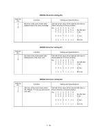
EEPROM Customizing, 3.10 Equipment Error Code Indication, The LCD shows the MACHINE ERROR X X
 |
View all Brother International IntelliFax-2600 manuals
Add to My Manuals
Save this manual to your list of manuals |
Page 135 highlights
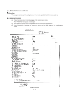
3.9 EEPROM Customizing Function This function allows you to customize the EEPROM according to language, function settings, and firmware switch settings. The customizing codes list is given in Appendix 1. NOTE: If you replace the main PCB, be sure to carry out this procedure. Operating Procedure (1) Press the 7 and 4 keys in this order in the initial stage of the maintenance mode. The current customizing code (e.g., 9101 in the case of MFC4300 U.S.A. versions) appears. (2) Enter the desired customizing code (e.g., 0002 in the case of MFC4600 Canadian versions). The newly entered code appears. NOTE: If a wrong 4-digit code is entered, the equipment will malfunction. (3) Press the Start key. The equipment saves the setting and returns to the initial stage of the maintenance mode. If you press the Stop key or no keys are pressed for one minute in the above procedure, the equipment stops the procedure and returns to the initial stage of the maintenance mode. 3.10 Equipment Error Code Indication Function This function displays an error code of the last error on the LCD. Operating Procedure (1) Press the 8 and 2 keys in this order in the initial stage of the maintenance mode. The LCD shows the "MACHINE ERROR X X." (2) To stop this operation and return the equipment to the initial stage of the maintenance mode, press the Stop key. V - 55
-
 1
1 -
2
-
3
-
4
-
5
-
6
-
7
-
8
-
9
-
10
-
11
-
12
-
13
-
14
-
15
-
16
-
17
-
18
-
19
-
20
-
21
-
22
-
23
-
24
-
25
-
26
-
27
-
28
-
29
-
30
-
31
-
32
-
33
-
34
-
35
-
36
-
37
-
38
-
39
-
40
-
41
-
42
-
43
-
44
-
45
-
46
-
47
-
48
-
49
-
50
-
51
-
52
-
53
-
54
-
55
-
56
-
57
-
58
-
59
-
60
-
61
-
62
-
63
-
64
-
65
-
66
-
67
-
68
-
69
-
70
-
71
-
72
-
73
-
74
-
75
-
76
-
77
-
78
-
79
-
80
-
81
-
82
-
83
-
84
-
85
-
86
-
87
-
88
-
89
-
90
-
91
-
92
-
93
-
94
-
95
-
96
-
97
-
98
-
99
-
100
-
101
-
102
-
103
-
104
-
105
-
106
-
107
-
108
-
109
-
110
-
111
-
112
-
113
-
114
-
115
-
116
-
117
-
118
-
119
-
120
-
121
-
122
-
123
-
124
-
125
-
126
-
127
-
128
-
129
-
 130
130 -
 131
131 -
 132
132 -
 133
133 -
 134
134 -
 135
135 -
 136
136 -
 137
137 -
 138
138 -
 139
139 -
 140
140 -
141
-
142
-
143
-
144
-
145
-
146
-
147
-
148
-
149
-
150
-
151
-
152
-
153
-
154
-
155
-
156
-
157
-
158
-
159
-
160
-
161
-
162
-
163
-
164
-
165
-
166
-
167
-
168
-
169
-
170
-
171
-
172
-
173
-
174
-
175
-
176
-
177
-
178
-
179
-
180
-
181
-
182
-
183
-
184
-
185
-
186
-
187
-
188
-
189
-
190
-
191
-
192
-
193
-
194
-
195
-
196
-
197
-
198
-
199
 |
 |
