Brother International IntelliFax-2600 Service Manual - Page 66
High-voltage Power Supply PCB
 |
View all Brother International IntelliFax-2600 manuals
Add to My Manuals
Save this manual to your list of manuals |
Page 66 highlights
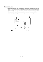
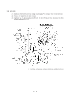
1.15 High-voltage Power Supply PCB (1) Remove the screw from the insulation film and high-voltage power supply PCB. (2) Remove the insulation film. (3) Slightly lift up the high-voltage power supply PCB and disconnect the main-high-voltage flat cable. (4) Disconnect the EL (eraser lamp) board harness and drum grounding harness from the highvoltage power supply PCB. Reassembling Notes • Before reinstalling the high-voltage power supply PCB, check the high-voltage contacts for any toner particles, paper dust or dirt, and clean them out. • Be sure to route the drum grounding harness through boss "x" and latches "y" and "z." • When putting the high-voltage power supply PCB back into place, first fit the cutout provided in the PCB over "a" and insert the rear edge under "b," and then secure the PCB together with the insulation sheet to the main cover with the screw. IV - 34
-
 1
1 -
2
-
3
-
4
-
5
-
6
-
7
-
8
-
9
-
10
-
11
-
12
-
13
-
14
-
15
-
16
-
17
-
18
-
19
-
20
-
21
-
22
-
23
-
24
-
25
-
26
-
27
-
28
-
29
-
30
-
31
-
32
-
33
-
34
-
35
-
36
-
37
-
38
-
39
-
40
-
41
-
42
-
43
-
44
-
45
-
46
-
47
-
48
-
49
-
50
-
51
-
52
-
53
-
54
-
55
-
56
-
57
-
58
-
59
-
60
-
 61
61 -
 62
62 -
 63
63 -
 64
64 -
 65
65 -
 66
66 -
 67
67 -
 68
68 -
 69
69 -
 70
70 -
 71
71 -
72
-
73
-
74
-
75
-
76
-
77
-
78
-
79
-
80
-
81
-
82
-
83
-
84
-
85
-
86
-
87
-
88
-
89
-
90
-
91
-
92
-
93
-
94
-
95
-
96
-
97
-
98
-
99
-
100
-
101
-
102
-
103
-
104
-
105
-
106
-
107
-
108
-
109
-
110
-
111
-
112
-
113
-
114
-
115
-
116
-
117
-
118
-
119
-
120
-
121
-
122
-
123
-
124
-
125
-
126
-
127
-
128
-
129
-
130
-
131
-
132
-
133
-
134
-
135
-
136
-
137
-
138
-
139
-
140
-
141
-
142
-
143
-
144
-
145
-
146
-
147
-
148
-
149
-
150
-
151
-
152
-
153
-
154
-
155
-
156
-
157
-
158
-
159
-
160
-
161
-
162
-
163
-
164
-
165
-
166
-
167
-
168
-
169
-
170
-
171
-
172
-
173
-
174
-
175
-
176
-
177
-
178
-
179
-
180
-
181
-
182
-
183
-
184
-
185
-
186
-
187
-
188
-
189
-
190
-
191
-
192
-
193
-
194
-
195
-
196
-
197
-
198
-
199
 |
 |
