Brother International IntelliFax-2600 Service Manual - Page 55
Brother International IntelliFax-2600 Manual
 |
View all Brother International IntelliFax-2600 manuals
Add to My Manuals
Save this manual to your list of manuals |
Page 55 highlights
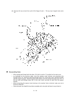
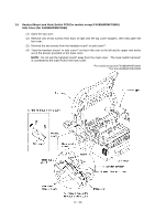
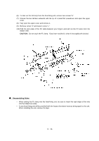
1.9 Handset Mount and Hook Switch PCB (for models except FAX8060P/MFC9060) Side Cover (for FAX8060P/MFC9060) (1) Open the top cover. (2) Remove one of two screws from each of right and left top cover stoppers, then fully open the top cover. (3) Remove the two screws from the handset mount* or side cover**. (4) Twist the handset mount* or side cover** so that it tilts over to the left and its upper end works out of the bosses provided on the main cover. NOTE: Do not pull the handset mount* away from the main cover. The hook switch harness* is connected to the main PCB in the main cover. *For models except the FAX8060P/MFC9060 **For the FAX8060P/MFC9060 IV - 23
-
 1
1 -
2
-
3
-
4
-
5
-
6
-
7
-
8
-
9
-
10
-
11
-
12
-
13
-
14
-
15
-
16
-
17
-
18
-
19
-
20
-
21
-
22
-
23
-
24
-
25
-
26
-
27
-
28
-
29
-
30
-
31
-
32
-
33
-
34
-
35
-
36
-
37
-
38
-
39
-
40
-
41
-
42
-
43
-
44
-
45
-
46
-
47
-
48
-
49
-
 50
50 -
 51
51 -
 52
52 -
 53
53 -
 54
54 -
 55
55 -
 56
56 -
 57
57 -
 58
58 -
 59
59 -
 60
60 -
61
-
62
-
63
-
64
-
65
-
66
-
67
-
68
-
69
-
70
-
71
-
72
-
73
-
74
-
75
-
76
-
77
-
78
-
79
-
80
-
81
-
82
-
83
-
84
-
85
-
86
-
87
-
88
-
89
-
90
-
91
-
92
-
93
-
94
-
95
-
96
-
97
-
98
-
99
-
100
-
101
-
102
-
103
-
104
-
105
-
106
-
107
-
108
-
109
-
110
-
111
-
112
-
113
-
114
-
115
-
116
-
117
-
118
-
119
-
120
-
121
-
122
-
123
-
124
-
125
-
126
-
127
-
128
-
129
-
130
-
131
-
132
-
133
-
134
-
135
-
136
-
137
-
138
-
139
-
140
-
141
-
142
-
143
-
144
-
145
-
146
-
147
-
148
-
149
-
150
-
151
-
152
-
153
-
154
-
155
-
156
-
157
-
158
-
159
-
160
-
161
-
162
-
163
-
164
-
165
-
166
-
167
-
168
-
169
-
170
-
171
-
172
-
173
-
174
-
175
-
176
-
177
-
178
-
179
-
180
-
181
-
182
-
183
-
184
-
185
-
186
-
187
-
188
-
189
-
190
-
191
-
192
-
193
-
194
-
195
-
196
-
197
-
198
-
199
 |
 |

IV
- 23
1.9
Handset Mount and Hook Switch PCB (for models except FAX8060P/MFC9060)
Side Cover (for FAX8060P/MFC9060)
(1)
Open the top cover.
(2)
Remove one of two screws from each of right and left top cover stoppers, then fully open the
top cover.
(3)
Remove the two screws from the handset mount* or side cover**.
(4)
Twist the handset mount* or side cover** so that it tilts over to the left and its upper end works
out of the bosses provided on the main cover.
NOTE:
Do not pull the handset mount* away from the main cover.
The hook switch harness*
is connected to the main PCB in the main cover.
*For models except the FAX8060P/MFC9060
**For the FAX8060P/MFC9060