Brother International IntelliFax-2600 Service Manual - Page 59
Laser Unit and Toner Sensor PCB, Do not disturb it.
 |
View all Brother International IntelliFax-2600 manuals
Add to My Manuals
Save this manual to your list of manuals |
Page 59 highlights
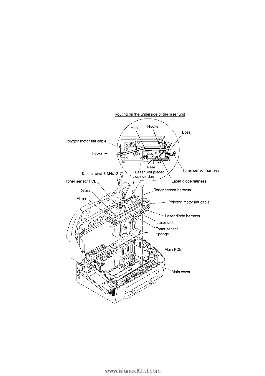
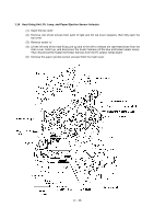
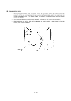
1.11 Laser Unit and Toner Sensor PCB (1) Remove the screw (Taptite, cup B M3x8) from the toner sensor PCB. (2) Slightly lift up the toner sensor PCB and disconnect its harness. (3) Remove the three screws from the laser unit. (4) Slightly lift up the laser unit and disconnect the following from the main PCB: - Laser diode harness (5-pin) - Toner sensor harness (4-pin) if the toner sensor PCB is installed - Polygon motor flat cable NOTE: When handling the laser unit, take care not to touch the inside of the unit, glass, or mirror. NOTE: On the small PCB at the right side of the laser unit is a 2-pin connector which is for the adjustment in the factory. Do not disturb it. Reassembling Notes • Before putting the laser unit back into place, check for any toner particles, paper dust or dirt, and clean them out. • When installing the laser unit, make sure that the laser diode harness, toner sensor harness and polygon motor flat cable are routed as shown above. • Make sure that the sponge is placed below the laser unit. IV - 27
-
 1
1 -
2
-
3
-
4
-
5
-
6
-
7
-
8
-
9
-
10
-
11
-
12
-
13
-
14
-
15
-
16
-
17
-
18
-
19
-
20
-
21
-
22
-
23
-
24
-
25
-
26
-
27
-
28
-
29
-
30
-
31
-
32
-
33
-
34
-
35
-
36
-
37
-
38
-
39
-
40
-
41
-
42
-
43
-
44
-
45
-
46
-
47
-
48
-
49
-
50
-
51
-
52
-
53
-
 54
54 -
 55
55 -
 56
56 -
 57
57 -
 58
58 -
 59
59 -
 60
60 -
 61
61 -
 62
62 -
 63
63 -
 64
64 -
65
-
66
-
67
-
68
-
69
-
70
-
71
-
72
-
73
-
74
-
75
-
76
-
77
-
78
-
79
-
80
-
81
-
82
-
83
-
84
-
85
-
86
-
87
-
88
-
89
-
90
-
91
-
92
-
93
-
94
-
95
-
96
-
97
-
98
-
99
-
100
-
101
-
102
-
103
-
104
-
105
-
106
-
107
-
108
-
109
-
110
-
111
-
112
-
113
-
114
-
115
-
116
-
117
-
118
-
119
-
120
-
121
-
122
-
123
-
124
-
125
-
126
-
127
-
128
-
129
-
130
-
131
-
132
-
133
-
134
-
135
-
136
-
137
-
138
-
139
-
140
-
141
-
142
-
143
-
144
-
145
-
146
-
147
-
148
-
149
-
150
-
151
-
152
-
153
-
154
-
155
-
156
-
157
-
158
-
159
-
160
-
161
-
162
-
163
-
164
-
165
-
166
-
167
-
168
-
169
-
170
-
171
-
172
-
173
-
174
-
175
-
176
-
177
-
178
-
179
-
180
-
181
-
182
-
183
-
184
-
185
-
186
-
187
-
188
-
189
-
190
-
191
-
192
-
193
-
194
-
195
-
196
-
197
-
198
-
199
 |
 |