Brother International IntelliFax-2600 Service Manual - Page 67
Fan, Put the fan back into place with the non-sponge end facing up and with the label side facing
 |
View all Brother International IntelliFax-2600 manuals
Add to My Manuals
Save this manual to your list of manuals |
Page 67 highlights
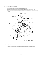
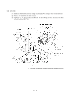
1.16 Fan (1) If the main PCB is installed, remove the screw from the main PCB (refer to Section 1.14). (2) Slightly lift up the main PCB and disconnect the fan harness from the main PCB. (3) Take out the fan support. (4) Pull up the fan. Reassembling Notes • Put the fan back into place with the non-sponge end facing up and with the label side facing outwards. • Route the fan harness through the harness guide as shown above. IV - 35
-
 1
1 -
2
-
3
-
4
-
5
-
6
-
7
-
8
-
9
-
10
-
11
-
12
-
13
-
14
-
15
-
16
-
17
-
18
-
19
-
20
-
21
-
22
-
23
-
24
-
25
-
26
-
27
-
28
-
29
-
30
-
31
-
32
-
33
-
34
-
35
-
36
-
37
-
38
-
39
-
40
-
41
-
42
-
43
-
44
-
45
-
46
-
47
-
48
-
49
-
50
-
51
-
52
-
53
-
54
-
55
-
56
-
57
-
58
-
59
-
60
-
61
-
 62
62 -
 63
63 -
 64
64 -
 65
65 -
 66
66 -
 67
67 -
 68
68 -
 69
69 -
 70
70 -
 71
71 -
 72
72 -
73
-
74
-
75
-
76
-
77
-
78
-
79
-
80
-
81
-
82
-
83
-
84
-
85
-
86
-
87
-
88
-
89
-
90
-
91
-
92
-
93
-
94
-
95
-
96
-
97
-
98
-
99
-
100
-
101
-
102
-
103
-
104
-
105
-
106
-
107
-
108
-
109
-
110
-
111
-
112
-
113
-
114
-
115
-
116
-
117
-
118
-
119
-
120
-
121
-
122
-
123
-
124
-
125
-
126
-
127
-
128
-
129
-
130
-
131
-
132
-
133
-
134
-
135
-
136
-
137
-
138
-
139
-
140
-
141
-
142
-
143
-
144
-
145
-
146
-
147
-
148
-
149
-
150
-
151
-
152
-
153
-
154
-
155
-
156
-
157
-
158
-
159
-
160
-
161
-
162
-
163
-
164
-
165
-
166
-
167
-
168
-
169
-
170
-
171
-
172
-
173
-
174
-
175
-
176
-
177
-
178
-
179
-
180
-
181
-
182
-
183
-
184
-
185
-
186
-
187
-
188
-
189
-
190
-
191
-
192
-
193
-
194
-
195
-
196
-
197
-
198
-
199
 |
 |

IV
- 35
1.16
Fan
(1)
If the main PCB is installed, remove the screw from the main PCB (refer to Section 1.14).
(2)
Slightly lift up the main PCB and disconnect the fan harness from the main PCB.
(3)
Take out the fan support.
(4)
Pull up the fan.
±
Reassembling Notes
•
Put the fan back into place with the non-sponge end facing up and with the label side facing
outwards.
•
Route the fan harness through the harness guide as shown above.