Cisco AIR-AP1242AG-A-K9 Hardware Installation Guide - Page 19
Single or Dual-Radio Operation, Antennas Supported, Ethernet Port, Console Port, LEDs - datasheet
 |
UPC - 882658021961
View all Cisco AIR-AP1242AG-A-K9 manuals
Add to My Manuals
Save this manual to your list of manuals |
Page 19 highlights
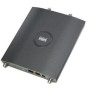
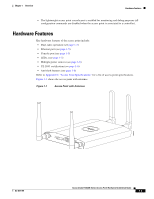
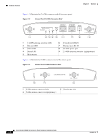
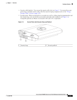
Chapter 1 Overview Hardware Features Single or Dual-Radio Operation The 1242AG access point supports simultaneous radio operation using a 2.4-GHz 802.11g radio and a 5-GHz 802.11a radio. The 1242G access point supports a single 2.4-GHz 802.11g radio. Each radio uses dual-diversity integrated antennas. The 5-GHz radio incorporates an Unlicensed National Information Infrastructure (UNII) radio transceiver operating in the UNII 5-GHz frequency bands. The 802.11g radio is called Radio0 and the 802.11a radio is called Radio1. Antennas Supported The 1242AG access point supports a wide range of antennas that you can connect to the RP-TNC connectors on the 2.4-GHz and 5-GHz radios. For a complete list fo supported antennas, refer to the Cisco Aironet 2.4 GHz and 5 GHz Antennas and Accessories datasheet at this URL: http://www.cisco.com/en/US/products/hw/wireless/ps469/products_data_sheets_list.html Ethernet Port The auto-sensing Ethernet port (see Figure 1-2) accepts an RJ-45 connector, linking the access point to your 10BASE-T or 100BASE-T Ethernet LAN. The access point can receive power through the Ethernet cable from a power injector, switch, or power patch panel. The Ethernet MAC address is printed on the label on the back of the access point (refer to the "Locating the Product Serial Number" section on page xiii). Console Port The serial console port can be used to monitor the access point power-up sequences using a terminal emulator program. The port is located on the end of the unit (see Figure 1-2). Use an RJ-45 to DB-9 serial cable to connect your computer's COM port to the access point's serial console port. (Refer to Appendix E, "Console Cable Pinouts," for a description of the console port pinouts.) Assign the following port settings to a terminal emulator to open the management system pages: 9600 baud, 8 data bits, No parity, 1 stop bit, and no flow control. Note After completing your configuration changes, you must remove the serial cable from the access point. LEDs The access point has three LEDs to indicate Ethernet activity, radio activity, and status indications (refer to the "Checking the Autonomous Access Point LEDs" section on page 3-2 or the "Checking the Lightweight Access Point LEDs" section on page 4-3 for additional information). Figure 1-2 shows the location of the LEDs. • The Status LED provides general operating status and error indications. • The Ethernet LED signals Ethernet traffic on the wired Ethernet LAN and provides Ethernet error indications. • The Radio LED signals that wireless packets are being transmitted or received over the radio interface and provides radio error indications. OL-8371-05 Cisco Aironet 1240AG Series Access Point Hardware Installation Guide 1-5
-
 1
1 -
2
-
3
-
4
-
5
-
6
-
7
-
8
-
9
-
10
-
11
-
12
-
13
-
 14
14 -
 15
15 -
 16
16 -
 17
17 -
 18
18 -
 19
19 -
 20
20 -
 21
21 -
 22
22 -
 23
23 -
 24
24 -
25
-
26
-
27
-
28
-
29
-
30
-
31
-
32
-
33
-
34
-
35
-
36
-
37
-
38
-
39
-
40
-
41
-
42
-
43
-
44
-
45
-
46
-
47
-
48
-
49
-
50
-
51
-
52
-
53
-
54
-
55
-
56
-
57
-
58
-
59
-
60
-
61
-
62
-
63
-
64
-
65
-
66
-
67
-
68
-
69
-
70
-
71
-
72
-
73
-
74
-
75
-
76
-
77
-
78
-
79
-
80
-
81
-
82
-
83
-
84
-
85
-
86
-
87
-
88
-
89
-
90
-
91
-
92
-
93
-
94
-
95
-
96
-
97
-
98
-
99
-
100
-
101
-
102
-
103
-
104
-
105
-
106
-
107
-
108
-
109
-
110
-
111
-
112
-
113
-
114
-
115
-
116
-
117
-
118
-
119
-
120
-
121
-
122
-
123
-
124
 |
 |