Cisco AIR-AP1242AG-A-K9 Hardware Installation Guide - Page 53
Checking Basic Settings
 |
UPC - 882658021961
View all Cisco AIR-AP1242AG-A-K9 manuals
Add to My Manuals
Save this manual to your list of manuals |
Page 53 highlights
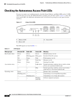
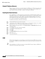
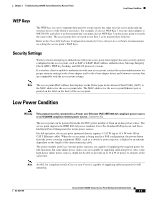
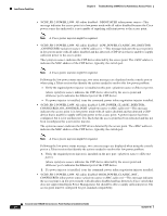
Chapter 3 Troubleshooting 1240AG Series Autonomous Access Points Checking Basic Settings Table 3-1 LED Signals (continued) Message type Ethernet LED Radio LED Status LED Meaning Boot loader warnings Off Off Yellow Ethernet link not operational. Red Off Yellow Ethernet failure. Amber Off Yellow Configuration recovery in progress (Mode button pressed for 2 to 3 seconds). Off Red Pink Image recovery (Mode button pressed for 20 to 30 seconds) Blinking green Blinking red Blinking pink Image recovery in progress and Mode button is released. Boot loader errors Red Red Red DRAM memory test failure. Off Red Blinking red Flash file system failure. and blue Off Amber Blinking red Environment variable (ENVAR) failure. and blue-green Amber Off Blinking red Bad MAC address. and yellow Red Off Blinking red Ethernet failure during image recovery. and off Amber Amber Blinking red Boot environment error. and off Red Amber Blinking red No Cisco IOS image file. and off Amber Amber Blinking red Boot failure. and off Cisco IOS errors Blinking - amber - Transmit or receive Ethernet errors. - Blinking amber - Maximum retries or buffer full occurred on the radio. Red Red Amber Software failure; try disconnecting and reconnecting unit power. - - Amber General warning, insufficient inline power (see the Low Power Condition section). Checking Basic Settings Mismatched basic settings are the most common causes of lost connectivity with wireless clients. If the access point does not communicate with client devices, check the following areas. OL-8371-05 Cisco Aironet 1240AG Series Access Point Hardware Installation Guide 3-3
-
 1
1 -
2
-
3
-
4
-
5
-
6
-
7
-
8
-
9
-
10
-
11
-
12
-
13
-
14
-
15
-
16
-
17
-
18
-
19
-
20
-
21
-
22
-
23
-
24
-
25
-
26
-
27
-
28
-
29
-
30
-
31
-
32
-
33
-
34
-
35
-
36
-
37
-
38
-
39
-
40
-
41
-
42
-
43
-
44
-
45
-
46
-
47
-
 48
48 -
 49
49 -
 50
50 -
 51
51 -
 52
52 -
 53
53 -
 54
54 -
 55
55 -
 56
56 -
 57
57 -
 58
58 -
59
-
60
-
61
-
62
-
63
-
64
-
65
-
66
-
67
-
68
-
69
-
70
-
71
-
72
-
73
-
74
-
75
-
76
-
77
-
78
-
79
-
80
-
81
-
82
-
83
-
84
-
85
-
86
-
87
-
88
-
89
-
90
-
91
-
92
-
93
-
94
-
95
-
96
-
97
-
98
-
99
-
100
-
101
-
102
-
103
-
104
-
105
-
106
-
107
-
108
-
109
-
110
-
111
-
112
-
113
-
114
-
115
-
116
-
117
-
118
-
119
-
120
-
121
-
122
-
123
-
124
 |
 |