Compaq Evo n800c Maintenance and Service Guide - Page 122
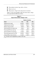
Table 5-1, Disassembly Sequence Chart, Description, of Screws Removed
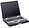 |
View all Compaq Evo n800c manuals
Add to My Manuals
Save this manual to your list of manuals |
Page 122 highlights
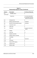
Removal and Replacement Procedures Table 5-1 Disassembly Sequence Chart (Continued) Section 5.3 (continued) Description MultiBay device Hard drive 5.4 Computer feet 5.5 Memory expansion board 5.6 Mini PCI communications board 5.7 Connector cover 5.8 LED cover 5.9 Keyboard 5.10 Display 5.11 Top cover 5.12 Speaker assembly 5.13 Display release assembly 5.14 TouchPad 5.15 Fan 5.16 Processor 5.17 Disk cell RTC battery 5.18 System board 5.19 Modem cable # of Screws Removed 0 1 to remove hard drive 2 to separate hard drive bezel from hard drive 0 1 loosened 1 loosened 2 2 2 to remove keyboard shield 4 16 0 2 4 4 loosened 0 0 5 0 Maintenance and Service Guide 5-3
-
 1
1 -
2
-
3
-
4
-
5
-
6
-
7
-
8
-
9
-
10
-
11
-
12
-
13
-
14
-
15
-
16
-
17
-
18
-
19
-
20
-
21
-
22
-
23
-
24
-
25
-
26
-
27
-
28
-
29
-
30
-
31
-
32
-
33
-
34
-
35
-
36
-
37
-
38
-
39
-
40
-
41
-
42
-
43
-
44
-
45
-
46
-
47
-
48
-
49
-
50
-
51
-
52
-
53
-
54
-
55
-
56
-
57
-
58
-
59
-
60
-
61
-
62
-
63
-
64
-
65
-
66
-
67
-
68
-
69
-
70
-
71
-
72
-
73
-
74
-
75
-
76
-
77
-
78
-
79
-
80
-
81
-
82
-
83
-
84
-
85
-
86
-
87
-
88
-
89
-
90
-
91
-
92
-
93
-
94
-
95
-
96
-
97
-
98
-
99
-
100
-
101
-
102
-
103
-
104
-
105
-
106
-
107
-
108
-
109
-
110
-
111
-
112
-
113
-
114
-
115
-
116
-
 117
117 -
 118
118 -
 119
119 -
 120
120 -
 121
121 -
 122
122 -
 123
123 -
 124
124 -
 125
125 -
 126
126 -
 127
127 -
128
-
129
-
130
-
131
-
132
-
133
-
134
-
135
-
136
-
137
-
138
-
139
-
140
-
141
-
142
-
143
-
144
-
145
-
146
-
147
-
148
-
149
-
150
-
151
-
152
-
153
-
154
-
155
-
156
-
157
-
158
-
159
-
160
-
161
-
162
-
163
-
164
-
165
-
166
-
167
-
168
-
169
-
170
-
171
-
172
-
173
-
174
-
175
-
176
-
177
-
178
-
179
-
180
-
181
-
182
-
183
-
184
-
185
-
186
-
187
-
188
-
189
-
190
-
191
-
192
-
193
-
194
-
195
-
196
-
197
-
198
-
199
-
200
-
201
-
202
-
203
-
204
-
205
-
206
-
207
-
208
-
209
-
210
-
211
-
212
-
213
-
214
-
215
-
216
-
217
-
218
-
219
-
220
-
221
 |
 |
Removal and Replacement Procedures
Maintenance and Service Guide
5–3
Section
Description
# of Screws Removed
5.3
(continued)
MultiBay device
0
Hard drive
1 to remove hard drive
2 to separate hard drive
bezel from hard drive
5.4
Computer feet
0
5.5
Memory expansion board
1 loosened
5.6
Mini PCI communications board
1 loosened
5.7
Connector cover
2
5.8
LED cover
2
5.9
Keyboard
2 to remove keyboard
shield
5.10
Display
4
5.11
Top cover
16
5.12
Speaker assembly
0
5.13
Display release assembly
2
5.14
TouchPad
4
5.15
Fan
4 loosened
5.16
Processor
0
5.17
Disk cell RTC battery
0
5.18
System board
5
5.19
Modem cable
0
Table 5-1
Disassembly Sequence Chart
(Continued)