D-Link DWS-3024 Product Manual
D-Link DWS-3024 - L2+ Gigabit Wireless Switch Manual
 |
UPC - 790069288760
View all D-Link DWS-3024 manuals
Add to My Manuals
Save this manual to your list of manuals |
D-Link DWS-3024 manual content summary:
- D-Link DWS-3024 | Product Manual - Page 1
- D-Link DWS-3024 | Product Manual - Page 2
D-Link Unified Access System User Manual FCC Warning This equipment has been tested and found to comply , angemessene Massnahmen zu ergreifen. Precaución! Este es un producto de Clase A. En un entorno doméstico, puede causar interferencias de radio, en cuyo case, puede requerirse al usuario para que - D-Link DWS-3024 | Product Manual - Page 3
Conventions 15 Safety Instructions 16 Safety Switch Deployment 24 Peer Unified Switch Deployment 24 Understanding the User Interfaces 25 Using the Web Interface 26 Using the Command-Line Interface 28 Using SNMP 29 Wireless System Features and Standards Support 30 2 Planning the D-Link - D-Link DWS-3024 | Product Manual - Page 4
D-Link Unified Access System User Manual Installing the Switch in a Rack 45 Powering On the Switch 46 Installing the SFP ports 46 Installing the Optional Modules 47 Connecting to the External Redundant Power System 49 Connecting the Switch 49 Connecting the Switch to the Network 50 Connecting - D-Link DWS-3024 | Product Manual - Page 5
Plan History 113 Initiating Manual Channel Plan Assignments 114 Initiating Manual Power Adjustments 115 Upgrading the Access Point Software 172 Monitoring and Configuring Captive Portal Users 174 Configuring Users in the Local Database 175 Configuring Users in a Remote RADIUS Server 176 - D-Link DWS-3024 | Product Manual - Page 6
D-Link Unified Access System User Manual Viewing Link Unified Access System Default Settings 203 Default D-Link Unified Switch Settings 203 Default D-Link Access Point Settings 204 Default D-Link of Service 229 QoS and Load Balancing 229 6 © 2001- 2008 D-Link Corporation. All Rights Reserved. - D-Link DWS-3024 | Product Manual - Page 7
Only 235 Product Registration 239 Limited Warranty 240 What You Must Do For Warranty Service 241 What Is Not Covered 241 Trademarks 242 Copyright Statement 242 FCC Warning 242 F Technical Support 243 International Offices 267 Registration Card All Countries and Regions Excluding USA 268 7 - D-Link DWS-3024 | Product Manual - Page 8
D-Link Unified Access System User Manual 8 © 2001- 2008 D-Link Corporation. All Rights Reserved. - D-Link DWS-3024 | Product Manual - Page 9
22. Inserting the Fiber-Optic Transceivers into the Switch 47 Figure 23. Front Panel of the DEM-410X 48 Figure 24. Front Panel of the DEM-410CX 48 Figure 25. Inserting the optional module into the Switch (DWS-3026 48 Figure 26. DWS-3026 with optional DEM-410X module installed 49 Figure 27 - D-Link DWS-3024 | Product Manual - Page 10
D-Link Unified Access System User Manual Figure 44. AP Network Security Manual Power Adjustments 115 Figure 54. AP Upgrade 116 Figure 55. AP Upgrade Status 117 Figure 56. Advanced AP Management 119 Figure 57. Global WLAN Status 124 Figure 58. Wireless Discovery Status 126 Figure 59. Peer Switch - D-Link DWS-3024 | Product Manual - Page 11
List of Figures Figure 90. Interface - Client Status 185 Figure 91. CP - Client Status 186 Figure 92. SNMP Trap Configuration 187 Figure 93. Sample WLAN Visualization 190 Figure 94. Multiple Graphs 194 Figure 95. List View and Tabbed View 194 Figure 96. Component Tool Tip 195 Figure 97. - D-Link DWS-3024 | Product Manual - Page 12
D-Link Unified Access System User Manual 12 © 2001- 2008 D-Link Corporation. All Rights Reserved. - D-Link DWS-3024 | Product Manual - Page 13
116 Table 20. AP Upgrade Status 118 Table 21. Advanced AP Management 119 Table 22. AP Debug 120 Table 23. Managed AP Channel/Power Adjust 120 Table 24. Global WLAN Statistics 124 Table 25. Peer Switch Status 127 Table 26. Monitoring All Access Points 128 Table 27. Managed Access Point - D-Link DWS-3024 | Product Manual - Page 14
D-Link Unified Access System User Manual Table 44. Associated Client SSID Status 149 Table 45. Table 74. WLAN Visualization Menu Bar Options 196 Table 75. Component Information 201 Table 76. Switch Defaults 203 Table 77. Default AP Settings 204 Table 78. AP Profile Default Settings 205 - D-Link DWS-3024 | Product Manual - Page 15
. Audience The information in this guide is intended for the person responsible for installing, configuring, monitoring, and maintaining the D-Link Unified Access System as part of a network infrastructure. Organization The D-Link Unified Access System User Manual contains the following chapters - D-Link DWS-3024 | Product Manual - Page 16
Link Unified Access System User Manual This guide switch-prompt)# show network value [value] [] {choice1 | choice2} choice1 | choice2 [{choice1 | choice2}] Safety Instructions outlet and replace the part or contact your trained service provider: - The power cable, extension cable, or - D-Link DWS-3024 | Product Manual - Page 17
gets wet, see the appropriate section in your troubleshooting guide or contact your trained service provider. • Do not push any objects into , consult your service provider or local power company. • To help avoid damaging your system, be sure the voltage selection Switch (if provided Instructions 17 - D-Link DWS-3024 | Product Manual - Page 18
Link Unified Access System User Manual General Precautions for Rack-Mountable Products Observe the following precautions for rack stability and safety. Also refer to the rack installation documentation accompanying the system and the rack for specific any component when servicing other components in - D-Link DWS-3024 | Product Manual - Page 19
battery is incorrectly replaced. Replace only with the same or equivalent type of battery recommended by the manufacturer. Discard used batteries according to the manufacturer's instructions. Safety Instructions 19 - D-Link DWS-3024 | Product Manual - Page 20
D-Link Unified Access System User Manual 20 © 2001- 2008 D-Link Corporation. All Rights Reserved. - D-Link DWS-3024 | Product Manual - Page 21
and Standards Support D-Link Unified Access System Components The D-Link Unified Access System components include the D-Link Unified Switch and the D-Link Access Point (AP). The DWS-3024L Unified Switch can manage up to 24 D-Link Access Points, whereas the DWS-3024 and the DWS-3026 switches can - D-Link DWS-3024 | Product Manual - Page 22
User Manual D-Link Unified Switch The D-Link Unified Switch handles Layer 2, 3, and 4 switching and routing functions for traffic on the wired and wireless LAN. The DWS-3024L manages up to 24 access points (APs), and the DWS-3024 and DWS-3026 switches manage up to 48 APs. The Unified Switch user - D-Link DWS-3024 | Product Manual - Page 23
building layout to customize the network view. Figure 1 shows an example of a floor plan and network with a D-Link Unified Switch that manages two APs. The graph also shows a peer switch and a rogue AP in the network. Figure 1. Sample WLAN Visualization The WLAN Visualization tool provides an AP - D-Link DWS-3024 | Product Manual - Page 24
Unified Access System User Manual Single Unified Switch Deployment When you deploy a D-Link Access Point, the D-Link Unified Switch can automatically detect the AP and assign a default profile, which includes automatic RF channel selection and automatic power adjustment. Figure 2 shows a deployment - D-Link DWS-3024 | Product Manual - Page 25
Overview of the D-Link Unified Access System up to 48 access points (DWS-3024 and DWS-3026) or 24 access points (DWS-3024L). The Unified Switch and the APs it manages do not need to be on the same subnet. Figure 3. Peer Unified Switch with Layer 3 Roaming Support Unified Switch 1 Remote Management - D-Link DWS-3024 | Product Manual - Page 26
D-Link Unified Access System User Manual Using the Web Interface The following Web browsers are supported for Web interface access to the switch: • Microsoft® Windows® Internet graphic is a Java™ applet that displays the ports on the D-Link Unified Switch. This graphic appears at the top of each - D-Link DWS-3024 | Product Manual - Page 27
1 Overview of the D-Link Unified Access System Click the port you want to view Interface without saving your changes. If you click the graphic but do not click a specific port, the main menu appears. This menu contains the same option as the navigation menu menus. Understanding the User Interfaces 27 - D-Link DWS-3024 | Product Manual - Page 28
Save Changes • Download File • Upload File • Multiple Image Services Each item in the list is a link to the Web supports specific commands. The commands in one mode are not available until you switch to that particular mode, with the exception of the User EXEC mode commands. You can execute the User - D-Link DWS-3024 | Product Manual - Page 29
users that can manage traps the SNMP agent generates. The D-Link Unified Switch uses both standard public MIBs for standard functionality as well as a number of additional private MIBs for additional functionality supported by the switch. All private MIBs begin with a "DLINK to select DES for the - D-Link DWS-3024 | Product Manual - Page 30
D-Link Unified Access System User Manual 7. Click Submit. To access configuration information for SNMPv1 or SNMPv2, click LAN > Administration > SNMP Manager and click the page that contains the information to configure. Wireless System Features and Standards Support In addition to core switching - D-Link DWS-3024 | Product Manual - Page 31
to 24 APs (DWS-3024L) or 48 APs (DWS-3024 and DWS-3026) per switch - Auto AP image download - D-Link WLAN Private MIB • Simultaneous AP upgrade • Centralized data forwarding via tunneling for fast roaming and unified QoS • AP RF Monitoring • Configuration & Firmware Upload/Download Each AP supports - D-Link DWS-3024 | Product Manual - Page 32
Link Unified Access System User Manual • WLAN Networking and QoS - Switch/AP Discovery - Tunneling - WMM (802.11e) - 802.1p (MAC layer QoS support) - DSCP - Dynamic VLANs - MAC ACLs - SpectralLink Priority Support IV avoidance - MAC Authentication - Port/IP blocking - RADIUS support - EAP - PEAP - - D-Link DWS-3024 | Product Manual - Page 33
-emulation software • Direct serial connection to the console port of the D-Link Unified Switch • Remote system for management access with a Web browser, Telnet/SSH client, or SNMP manager To support security and networking features in D-Link Unified Access System, you can use the following optional - D-Link DWS-3024 | Product Manual - Page 34
User Manual Figure 7 shows a simple D-Link Unified Access System deployment with required and optional equipment for setup and operation. Figure 7. D-Link Unified Access System Components AP 1 Unified Switch portable or built-in Wi-Fi client adapter that supports one or more of the IEEE 802.11 - D-Link DWS-3024 | Product Manual - Page 35
the 10/100/1000 Mbps Ethernet ports on the switch. All connections to the D-Link Unified Switch must be wired connections since the switch does not have any radios. In Figure 8, the D-Link Unified Switches are both LAN and WLAN switches that handle traffic from end users connected to the wired LAN - D-Link DWS-3024 | Product Manual - Page 36
Unified Access System User Manual Figure 9 shows two D-Link Unified Switches in the network data center. In this deployment, the switches do not connect directly to APs or end-user nodes. Figure 9. Data Center Topology LAN Switch Unified Switches APs Network Backbone LAN Switch Data Center APs - D-Link DWS-3024 | Product Manual - Page 37
needs of the network environment. Network Planning to Support Layer 3 Roaming With the D-Link Unified Access System, mobile stations can maintain their be directly attached to the Unified Switch or it may be located several router hops away from the Unified Switch. To support layer 3 roaming, it is - D-Link DWS-3024 | Product Manual - Page 38
Unified Access System User Manual The D-Link Unified Access System provides two ways to prevent the IP Switch. Routing must be enabled on the switch to support L3 roaming. Figure 10 shows a single wireless client as it roams among three APs in three different subnets. A D-Link Unified Switch - D-Link DWS-3024 | Product Manual - Page 39
the Hardware This chapter provides instructions for installing the D-Link DWS-3024, DWS-3024L, and DWS-3026 switch hardware. The following sections describe Installing the Switch without the Rack - Installing the Switch in a Rack - Powering On the Switch - Installing the SFP ports - Installing - D-Link DWS-3024 | Product Manual - Page 40
Unified Access System User Manual Front Panel Components The front panel of the Switch consists of LED indicators for Power, Console, RPS, PoE, and Link/Act/Speed for each port on the Switch including 10GE Ports for optional modules and SFP port LEDs. Table 2 describes the LED indicators in more - D-Link DWS-3024 | Product Manual - Page 41
LED Indicators The Switch supports LED indicators for Power, Console, RPS, PoE, and Port LEDs including 10GE port LEDs for optional module inserts on the DWS-3026. Figure 14. LED Indicators on DWS-3024L Figure 15. LED Indicators on DWS-3024 Figure 16. LED Indicators on DWS-3026 Hardware Overview 41 - D-Link DWS-3024 | Product Manual - Page 42
Unified Access System User Manual The following table describes the LEDs and the Mode Select Button on the front panel of each Switch. Table 2. LED Description LED Power Console RPS Link/Act/Speed and PoE Mode Port LEDs Description This LED lights green after powering the Switch on to indicate - D-Link DWS-3024 | Product Manual - Page 43
Table 2. LED Description LED 10GE Port LEDs Combo SFP Ports Description (DWS-3026 only) A steady green light denotes a valid link on the port while a blinking green light indicates activity on the port. These LEDs remain dark if there is no link/activity on the port. The LED indicators for the - D-Link DWS-3024 | Product Manual - Page 44
D-Link Unified Access System User Manual Installation This section describes how to install the Switch on a flat surface or in a standard equipment rack. It also describes how to install the optional components for the Switch. Package Contents Open the shipping carton of the Switch and carefully - D-Link DWS-3024 | Product Manual - Page 45
ventilation space between the Switch and any other objects in the vicinity. Figure 19. Prepare Switch for Installation on a Desktop or Shelf Rubber Feet Installing the Switch in a Rack The Switch can be mounted in a standard 19" rack. Use the following diagrams as a guide. Figure 20. Fasten Mounting - D-Link DWS-3024 | Product Manual - Page 46
the SFP ports The DWS-3000 series switches are equipped with SFP (Small Form-factor Pluggable) ports, which are to be used with fiber-optical transceiver cabling in order to uplink various other networking devices for a gigabit link that may span great distances. These SFP ports support full-duplex - D-Link DWS-3024 | Product Manual - Page 47
ports in the Switch. Figure 22. Inserting the Fiber-Optic Transceivers into the Switch Installing the Optional Modules The rear panel of the DWS-3026 includes the switch to transmit data at a rate of ten gigabits per second. The module port(s) are compliant with standard IEEE 802.3ae, support full- - D-Link DWS-3024 | Product Manual - Page 48
D-Link Unified Access System User Manual The front panels of the available modules are shown here: Figure 23. Front Panel of the DEM-410X Figure 24. Front Panel of the DEM-410CX Install the Module Unplug the Switch before removing the faceplate covering the empty slot. To install the module, slide - D-Link DWS-3024 | Product Manual - Page 49
ends of the module into the available screw holes on the Switch. The upgraded Switch is now ready for use. Figure 26. DWS-3026 with optional DEM-410X module installed Connecting to the External Redundant Power System The Switch supports an external redundant power system (RPS). The diagrams below - D-Link DWS-3024 | Product Manual - Page 50
D-Link Unified Access System User Manual Connecting the Switch to the Network You can use any of the 1000BASE-T ports, 10GB ports, or fiber-optic ports to connect the Switch to your network. The type of port you use to connect the switch depends on your network requirements and the type of node to - D-Link DWS-3024 | Product Manual - Page 51
cable or Category 5e copper cable, depending on the type of port. A valid connection is indicated when the Link LED is lit. Figure 30 shows the rear panel of the DWS-3026 with the optional DEM-410X module. Figure 30. Switch Connected to Network Core Fiber Optic Cable Core Network Connecting the - D-Link DWS-3024 | Product Manual - Page 52
D-Link Unified Access System User Manual 52 © 2001- 2008 D-Link Corporation. All Rights Reserved. - D-Link DWS-3024 | Product Manual - Page 53
by wireless clients and to minimize radio frequency (RF) interference by other access points. You should also determine how to integrate the D-Link Unified Switch into your existing network topology. For more information about planning the WLAN topology, see "WLAN Topology Considerations" on page 34 - D-Link DWS-3024 | Product Manual - Page 54
Unified Access System User Manual enabled in order for the switch to discover and validate D-Link Access Points. If the routing mode is disabled, the Unified Switch function uses the IP address of the network interface. If routing is enabled, the switch uses a loopback or routing interface for the - D-Link DWS-3024 | Product Manual - Page 55
switch through the console port (RS-232 DCE). After you connect to the switch, you can provide network information or enable the DHCP client. To connect to the switch the return key, and the User: prompt appears. Enter admin as the user name. There is no bootp. - To manually configure the IP address - D-Link DWS-3024 | Product Manual - Page 56
System User Manual To view the network information, enter show network. 6. To save these changes so they are retained during a switch reset, enter the following command: write Once the D-Link Unified Switch is connected to the network, you can use the IP address for remote access to the switch by - D-Link DWS-3024 | Product Manual - Page 57
be enabled. For information about how to configure a loopback interface and enable routing, see "D-Link Unified Switch with Routing Enabled" on page 65. This field shows the IP address of the WLAN interface on the switch. If routing is disabled, the IP address is the network interface. If routing is - D-Link DWS-3024 | Product Manual - Page 58
Link Unified Access System User Manual The CLI commands to set the country code and enable the WLAN switch are available in Wireless Config mode. To set the country code, enter country-code . To enable the WLAN switch port on the access point and the other end of the cable to the Ethernet port - D-Link DWS-3024 | Product Manual - Page 59
user name and admin as the password. After a successful login, the DLINK-WLAN-AP# prompt appears. For information about how to disable the DHCP client on the AP or to set a static IP address, see "D-Link Access Point" on page 67 in the Assigning the IP Address to Switches .1X port-based supports MD5 - D-Link DWS-3024 | Product Manual - Page 60
Link Unified Access System User Manual In the following example, the administrator enables the 802.1X supplicant and sets the user name to wlanAP and the password to test1234. WLAN-AP# set dot1x-supplicant status up WLAN-AP# set dot1x-supplicant user on the Unified Switch. To configure the - D-Link DWS-3024 | Product Manual - Page 61
have their own IP address, must be able to find other WLAN devices, and must be compatible. When the D-Link Unified Switch discovers and validates D-Link Access Points, the switch takes over the management of the AP. The default AP Profile settings are listed in Appendix A. For information about - D-Link DWS-3024 | Product Manual - Page 62
D-Link Unified Access System User Manual address, either statically or through DHCP, the Unified Switch automatically discovers the AP through its broadcast of a L2 discovery message. Figure 32. L2 Discovery Example L2 Discovery Message Access Point Unified Switch In this example, the - D-Link DWS-3024 | Product Manual - Page 63
connects to the access point CLI and statically configures the IP addresses of two D-Link Unified Switches that are allowed to manage the AP. Figure 34. L3 Discovery Example 2 Unified Switch IP List 192.168.3.1.54 192.168.22.161 AP UDP Discovery Message (5 UDP SeconMdsesLsaDatiegsrec - D-Link DWS-3024 | Product Manual - Page 64
D-Link Unified Access System User Manual The AP can learn up to four Unified Switch IP specific switch, use one of the following methods: • Disable L2 Discovery on all switches and configure the IP address of the AP in only one Unified Switch. • Configure the IP address of one Unified Switch - D-Link DWS-3024 | Product Manual - Page 65
This can avoid discovery problems for the discovery modes that use the IP address of the Unified Switch. With the loopback switch to Global Config mode: (switch-prompt) User: admin Password: (switch-prompt) >enable Password: (switch-prompt) #config (switch-prompt) (Config)# 2. Enable routing. (switch - D-Link DWS-3024 | Product Manual - Page 66
D-Link Unified Access System User Manual 3. Change to Interface Config mode for loopback interface 0, and assign an IP address and subnet mask. (switch-prompt) (Config)#interface loopback 0 (switch-prompt) (Interface loopback 0)#ip address 10.1.1.1 255.255.0.0 4. [Optional] Change to Interface - D-Link DWS-3024 | Product Manual - Page 67
by using one of following four mechanisms: • Use VLANs to broadcast the D-Link Wireless Device Discovery Protocol. • Connect to the access point CLI and manually add the IP address of the switch. • Configure a DHCP server to include the switch IP address in the DHCP response to the AP DHCP client - D-Link DWS-3024 | Product Manual - Page 68
Unified Access System User Manual its association unless the connectivity to the current Unified Switch fails or the switch tells the AP to disassociate and associate with another switch. The following sections describe each discovery mechanism. D-Link Wireless Device Discovery Protocol The Wireless - D-Link DWS-3024 | Product Manual - Page 69
-prompt) #show wireless ap status Configuring IP Addresses of Peers and APs in the Switch You can configure up to 256 IP addresses for potential peer switches and APs in the D-Link Unified Switch. The switch sends association invitations to all IP addresses in this list. If the device accepts the - D-Link DWS-3024 | Product Manual - Page 70
Link Unified Access System User Manual Table 6. L3/IP Discovery Field Description L3/IP Discovery This check box is used to enable or disable IP-based discovery of access points and peer Unified Switches. When checked, IP polling is enabled and the switch number of entries supported is 256. IP - D-Link DWS-3024 | Product Manual - Page 71
Configuration Saved! To check the managed AP status from the Unified Switch CLI, enter the following command: (switch-prompt) #show wireless ap status Setting the Switch IP Address in the D-Link Access Point You can connect to the D-Link Access Point CLI and statically set the IP address or DNS name - D-Link DWS-3024 | Product Manual - Page 72
D-Link Unified Access System User Manual for AP association, but you can only use one switch to manage the AP. The other three switches are backup or alternate switches. Once you configure the AP with the IP addresses or DNS names of switches, the AP will only associate with those switches. Even if - D-Link DWS-3024 | Product Manual - Page 73
of up to four D-Link Unified Switches to the access point in DHCP option 43. If you configured a static IP address in the D-Link Access Point, the AP the Available Options list, scroll to Option 43 and select the 043 Vendor Specific Info check box. 3. Enter the Option 43 data into the Data Entry - D-Link DWS-3024 | Product Manual - Page 74
User Manual The following image shows the four IP addresses entered into the Data Entry field on the Windows DHCP server. 4. Click OK. The following figure shows a scope with Option 43 configured. Scope with Configured Option 43 Information Authenticating and Validating Access Points For a D-Link - D-Link DWS-3024 | Product Manual - Page 75
4 Installing the D-Link Unified Access System by another Unified Switch, it looks up the MAC address of the AP in the local or RADIUS Valid AP database. If it finds the MAC address in the database, the switch validates the AP and assumes management. If you have not added the MAC address of the - D-Link DWS-3024 | Product Manual - Page 76
D-Link Unified Access System User Manual To enable AP authentication on the Unified Switch, click Administration > Basic Setup. the settings for the APs in the database. All of the configuration takes place on the switch. To set up the local database for AP MAC Validation, use the following steps: 1. - D-Link DWS-3024 | Product Manual - Page 77
Link Unified Access System 4. In the MAC Address field, enter the MAC address of the AP to validate, and enter the physical location of the AP in the second field, then click Add. NOTE: If the switch for good security, you should enter at least 24 characters. 6. Use the default settings or configure - D-Link DWS-3024 | Product Manual - Page 78
D-Link Unified Access System User Manual The following example shows how to configure the local database by using the CLI: 1. Log on to the switch and enter Wireless Config Mode. (switch-prompt) >enable Password: (switch-prompt) #config (switch-prompt) (Config)#wireless 2. Set the local database as - D-Link DWS-3024 | Product Manual - Page 79
)#radius server host auth 192.168.2.2 (switch-prompt) (Config)#radius server key auth 192.168.2.2 Enter secret (16 characters max Re-enter secret For information about configuring additional RADIUS parameters by using the CLI, see the D-Link CLI Command Reference. Authenticating and Validating - D-Link DWS-3024 | Product Manual - Page 80
D-Link Unified Access System User Manual Managing Failed or Rogue APs If an AP attempts to contact a switch but the authentication fails or if the MAC address of an AP is not in the Valid AP database, AP Validation fails and the AP - D-Link DWS-3024 | Product Manual - Page 81
4 Installing the D-Link Unified Access System NOTE: If you select multiple APs to manage, the Web interface displays the selected APs in the MAC Address field one by - D-Link DWS-3024 | Product Manual - Page 82
D-Link Unified Access System User Manual 82 © 2001- 2008 D-Link Corporation. All Rights Reserved. - D-Link DWS-3024 | Product Manual - Page 83
for the AP. You can configure all of the AP settings directly from the switch before or after you validate the AP. The D-Link Unified Access System utilizes the DLink Wireless AP Protocol (DWAPP) for the switch to discover, configure, manage, and monitor the APs. This chapter describes the AP - D-Link DWS-3024 | Product Manual - Page 84
D-Link Unified Access System User Manual profile to assign each AP that the switch manages. An existing profile and or the RADIUS server does not return a VLAN for a specific client. Local Access Point Database In order for a Unified Switch to manage an access point, you must add the physical MAC - D-Link DWS-3024 | Product Manual - Page 85
that the access point uses. You can also manually set the channel and RF signal transmit power level Configuring AAA and RADIUS Settings In the D-Link Unified Access System, you can use a and communicates with the RADIUS server. The Unified Switch does not tunnel packets between the AP and RADIUS - D-Link DWS-3024 | Product Manual - Page 86
D-Link Unified Access System User Manual Table 7. Global RADIUS Server Field Secret Accounting Description The key as you type. RADIUS Accounting allows you to track and measure the resources a particular user has consumed such as system time and amount of data transmitted and received. NOTE: If - D-Link DWS-3024 | Product Manual - Page 87
to allow or deny access to all APs that use this profile. Configuring Wireless Radio Settings The DWL-3500AP supports one radio that operates in IEEE 802.11g mode. The DWL8500AP supports two radios: Radio 1 operates in IEEE 802.11a mode, and Radio 2 operates in IEEE 802.11g mode. The difference - D-Link DWS-3024 | Product Manual - Page 88
D-Link Unified Access System User Manual NOTE: The radio settings for the IEEE 802 you turn off a radio, the AP sends disassociation frames to all the wireless clients it is currently supporting so that the radio can be gracefully shutdown and the clients can start the association process with other - D-Link DWS-3024 | Product Manual - Page 89
scan other channels. Enabling this mode causes the radio to interrupt user traffic, which may be noticeable with voice connections. Changing the clients. In sentry mode, all VAPs are disabled. In this mode, the radio switches from one channel to the next. The length of time spent on each channel - D-Link DWS-3024 | Product Manual - Page 90
D-Link Unified Access System User Manual Table 9. Radio Settings Field Station Isolation Rate Sets Basic Supported Mode Maximum Clients of its supported rate sets. These numbers indicate rates that the access point supports. You can check multiple rates (click a check box to select or de-select a - D-Link DWS-3024 | Product Manual - Page 91
for auto-channel selection. You can automatically or manually run the autochannel selection algorithm to allow the Unified Switch to adjust the channel on APs as WLAN conditions 165. Some legacy 802.11a adapters might not support these higher channel numbers. Configuring Wireless Radio Settings 91 - D-Link DWS-3024 | Product Manual - Page 92
D-Link Unified Access System User Manual Table 9. Radio Settings Field Automatic Power Initial Power Antenna Diversity Description The power level affects how far attempts on frame sizes greater than the RTS Threshold. The range is 1-255. 92 © 2001- 2008 D-Link Corporation. All Rights Reserved. - D-Link DWS-3024 | Product Manual - Page 93
access point (V1AP) settings associated with the default AP profile. Each VAP has an associated network, which is identified by its network number and Service Set Identifier (SSID). You can configure and enable up to 8 VAPs per radio on each physical access point. Figure 39. VAP Settings VAPs - D-Link DWS-3024 | Product Manual - Page 94
D-Link Unified Access System User Manual The following table describes the fields on the SSID page. by its Service Set Identifier (SSID), which is an alphanumeric key that identifies a wireless local area network. You can configure up to 64 different networks on the D-Link Unified Switch. Each - D-Link DWS-3024 | Product Manual - Page 95
5 Configuring Access Point Settings When you click Edit on the VAP page, the Wireless Network Configuration page appears, as Figure 40 shows. Figure 40. Configuring Network Settings Table 12 describes the fields on the Wireless Network Configuration page. After you change the wireless network - D-Link DWS-3024 | Product Manual - Page 96
Link Unified Access System User Manual bandwidth, and are isolated on that network. The D-Link Unified Access System supports the configuration of a wireless VLAN. You can configure the wireless network topology changes (for example, a DWS-3000 switch reboots) while the L3 tunneling feature is in use - D-Link DWS-3024 | Product Manual - Page 97
appear, and any network settings that you modified are applied to the switch. "Configuring AP Security" on page 101 describes the security mechanisms fields you can configure if you select WEP or WPA/WPA2. D-Link's Adaptable Wireless technology provides you with the choice to associate a wireless - D-Link DWS-3024 | Product Manual - Page 98
D-Link Unified Access System User Manual Enabling and Configuring Additional VAPs When a wireless client searches for available wireless networks, each VAP you enable on the VAP tab appears as a separate network - D-Link DWS-3024 | Product Manual - Page 99
5 Configuring Access Point Settings In this example, the administrator configured multiple VAPs based on different functional groups within the company. Each VAP has a different SSID, security settings, and VLAN ID to separate traffic. You can associate the same network (SSID) with multiple VAPs. - D-Link DWS-3024 | Product Manual - Page 100
Access System User Manual In general, only clients that transmit and receive time-sensitive data while roaming need to take advantage of this feature. Figure 43 shows a network with two APs that are controlled by a D-Link Unified Switch. The APs and switch are all on different subnets. Figure - D-Link DWS-3024 | Product Manual - Page 101
a DWS-3000 switch reboots that any data transferred between the D-Link Access Point and the associated wireless during initial network configuration or for problem solving, but it is not 24-bit initialization vector (IV)), 128-bit (104-bit secret key + 24-bit IV), or 152-bit (128-bit secret key + 24 - D-Link DWS-3024 | Product Manual - Page 102
D-Link Unified Access System User Manual If you select WEP as the Security Mode, additional fields the RADIUS server For information about how to configure the global RADIUS server settings on the Unified Switch, see "Configuring AAA and RADIUS Settings" on page 85. Choose the authentication type: • - D-Link DWS-3024 | Product Manual - Page 103
and all clients must have one of the WEP keys specified on the AP in order to de-code AP-tostation data transmissions. • The AP must have all keys used by clients for station-to- check of credentials. The WAP/WPA2 Enterprise uses a RADIUS server to authenticate users. Configuring SSID Settings 103 - D-Link DWS-3024 | Product Manual - Page 104
D-Link Unified Access System User Manual If you select WPA/WPA2 as the security mode, Switch, see "Configuring AAA and RADIUS Settings" on page 85. Select the types of client stations you want to support: • WPA. If all client stations on the network support the original WPA but none support the - D-Link DWS-3024 | Product Manual - Page 105
that connect by using WPA2 can use this feature. It is not supported by the original WPA. Enter the number of pre-authentications that can RADIUS server returns a longer time in the Session-Timeout attribute for a particular user. The valid values of this are from 1-1440 minutes. NOTE: This field - D-Link DWS-3024 | Product Manual - Page 106
D-Link Unified Access System User Manual Configuring Valid Access Point Settings You can add an AP into apply the profile to the selected APs. If you use the local database for AP validation, the switch maintains the database of access points that you validate. When you add the MAC address of an AP - D-Link DWS-3024 | Product Manual - Page 107
log on to the AP itself and manage it by using the Administrator Web User Interface (UI) or CLI. • WS Managed-The AP is part of the D-Link Unified Access System, and you manage it by using the D-Link Unified Switch. If an AP is in Managed Mode, the Administrator Web UI on the - D-Link DWS-3024 | Product Manual - Page 108
Link Unified Access System User Manual 802.11b/802.11g modes (802.11 b/g) support use of channels 1 through 11 inclusive, while IEEE 802.11a mode supports a larger set of non-consecutive channels ( the AP and any automatic channel planning done by the switch. NOTE: For radios that use 802.11a mode, - D-Link DWS-3024 | Product Manual - Page 109
Link Access Points on your D-Link Unified Access System network: • Resetting the Access Points • Managing Radio Frequency Settings • Upgrading CLI, see the D-Link CLI Command Reference. Resetting the Access Points You can manually reset one or all APs from the D-Link Unified Switch. When you issue - D-Link DWS-3024 | Product Manual - Page 110
Link Unified Access System User Manual The APs might take several minutes to reset and re-establish communication with the switch the 2.4 GHz RF frequency and support use of channels 1 through 11. IEEE 802.11a mode operates in the 5 GHz frequency and supports a larger set of non-consecutive channels - D-Link DWS-3024 | Product Manual - Page 111
6 Managing and Maintaining D-Link Access Points Additionally, radios configured to use Super A or Super G cannot use the channel plan algorithm. NOTE: If the AP is not assigned a fixed channel or is not assigned a specific channel by the automatic channel selection algorithm, the AP channel - D-Link DWS-3024 | Product Manual - Page 112
D-Link Unified Access System User Manual Table 17. RF Channel Plan and Power Adjustment Field the interval to be from every 6 to every 24 hours. The interval period begins when you click Submit. The channel plan history lists the channels the switch assigns each of the APs it manages after a - D-Link DWS-3024 | Product Manual - Page 113
database and RADIUS server always override power set in the profile setting. If you manually set the power, the level is fixed and the AP will not use mode to Interval. Viewing the Channel Plan History The D-Link Unified Switch stores channel assignment information for the APs it manages. To - D-Link DWS-3024 | Product Manual - Page 114
D-Link Unified Access System User Manual Table 18 describes the Channel Plan History fields Table 18. date and time when the channel plan algorithm last ran. NOTE: To set the system time on the switch, you must use SNTP, which is disabled by default. From the Web interface, you configure the SNTP - D-Link DWS-3024 | Product Manual - Page 115
6 Managing and Maintaining D-Link Access Points The Current Status of the plan shows one of the following states: • None-The channel plan algorithm has not been manually run since the last switch reboot. • Algorithm In Progress-The channel plan algorithm is running. • Algorithm Complete-The channel - D-Link DWS-3024 | Product Manual - Page 116
the Access Point Software The D-Link Unified Switch can upgrade software on the APs that it manages. To upgrade one or more D-Link Access Point from the switch that manages it, click the WLAN > AP Management > Software Downloads tab. Figure 54. AP Upgrade NOTE: The APs automatically reset after - D-Link DWS-3024 | Product Manual - Page 117
Link Access Points Table 19. AP Upgrade Field File Name Group Size Managed AP Description Enter the name of the upgrade file. You may enter up to 32 characters, and the file extension ".tar" must be included. When you upgrade multiple APs, each AP contacts the TFTP server to download the upgrade - D-Link DWS-3024 | Product Manual - Page 118
User Manual Table 20 describes the fields that appear after you start the AP upgrade process. Table 20. AP Upgrade Status Field Download Status Download Count Success Count Failure Count Description This field shows the status of the upgrade process for all APs: • Not Started-The Unified Switch - D-Link DWS-3024 | Product Manual - Page 119
on the AP Management > Advanced page. From the Advanced page, you can also manually change the RF channel and power for each radio on an AP. Figure 56. Advanced AP Management Each AP managed by the D-Link Unified Switch is listed by its MAC address and location. The location is based on the - D-Link DWS-3024 | Product Manual - Page 120
User Manual Enabling AP Debugging You can enable debugging on an AP to allow Telnet access to the access point. Once you Telnet to the AP, you can issue commands from the CLI to help you troubleshoot. The fields in Table 22 appear when you click the Debug link if the AP or switch is reset. The - D-Link DWS-3024 | Product Manual - Page 121
6 Managing and Maintaining D-Link Access Points Table 23. Managed AP Channel/Power Mode of the radio interface. IEEE 802.11b/802.11g modes (802.11 b/g) support use of channels 1 through 11 inclusive, while IEEE 802.11a mode supports a larger set of nonconsecutive channels (36,40,44, 48, 52, 56, - D-Link DWS-3024 | Product Manual - Page 122
D-Link Unified Access System User Manual 122 © 2001- 2008 D-Link Corporation. All Rights Reserved. - D-Link DWS-3024 | Product Manual - Page 123
status and statistics by using the CLI, see the D-Link CLI Command Reference. Monitoring Wireless Global Information The D-Link Unified Switch periodically collects information from the D-Link Access Points it manages and from peer switches that are associated with it. The information on the Global - D-Link DWS-3024 | Product Manual - Page 124
User Manual For more information about an item on the Wireless Global Status page, click the value associated with the item to go to its status page. Figure 57. Global WLAN Status Table 24 describes the fields on the Wireless Global Status page. Table 24. Global WLAN Statistics Field WLAN Switch - D-Link DWS-3024 | Product Manual - Page 125
7 Monitoring Status and Statistics Table 24. Global WLAN Statistics Field Total Access Points Standalone Points." Total number of detected D-Link Access Points that are in Standalone Mode. APs in Standalone Mode are not currently managed by a D-Link Unified Switch. Number of APs in the managed - D-Link DWS-3024 | Product Manual - Page 126
D-Link Unified Access System User Manual Viewing IP Discovery Status From the Monitoring > Global > IP Discovery list and has authenticated or validated the device. • Discovered - Failed-The switch contacted the peer switch or AP with IP address in the L3/IP Discovery list and was unable to - D-Link DWS-3024 | Product Manual - Page 127
which can be one of the following methods: • L2 Poll • IP Poll Time since last communication with the switch in Hours, Minutes, and Seconds. Monitoring All Access Points The Monitoring > Access Points > All Access Points page shows summary information about managed, failed, and rogue - D-Link DWS-3024 | Product Manual - Page 128
Link Unified Access System User Manual The font color for the AP listing indicates that the AP is one of the following types: • Green-Managed AP • Red-Failed AP • Gray-Rogue AP • Amber-Peer Managed AP You can manually server). The physical port (in the slot/port format) on the switch that the AP is - D-Link DWS-3024 | Product Manual - Page 129
a failed status during a reset. • Rogue-The AP has not attempted to contact the switch, and the MAC address of the AP is not in the Valid AP database. • each radio on the AP is using. The D-Link DWL-3500AP access point has one radio, and the D-Link DWL-8500AP access point has two radios. Shows the - D-Link DWS-3024 | Product Manual - Page 130
Link Unified Access System User Manual Monitoring Managed Access Point Status From the Monitoring > Access Points > Managed Access Points page, you can access a variety of information about each AP that the switch radio interface on the APs that the switch manages. Table 27 describes the fields you - D-Link DWS-3024 | Product Manual - Page 131
Radio Channel Authenticated Clients Description The physical port (in the slot/port format) on the switch that the AP is connected to either directly each radio on the AP is using. The D-Link DWL-3500AP access point has one radio, and the D-Link DWL-8500AP access point has two radios. Shows the - D-Link DWS-3024 | Product Manual - Page 132
Link Unified Access System User Manual Viewing Detailed Managed Access Point Status To view detailed information about an AP that the switch Managed Access Point Status Field MAC Address Location Hardware Type Switch Port IP Address Profile Status Discovery Reason Description The label at - D-Link DWS-3024 | Product Manual - Page 133
Download the AP is not operational. Indicates the protocol version supported by the software on the AP, this is switch. The Managed Access Point Radio Summary page shows the channel, transmit power, and number of associated wireless clients for all managed APs. For more information about a specific - D-Link DWS-3024 | Product Manual - Page 134
Link Unified Access System User Manual detailed information about each radio on the APs that the Unified Switch manages on the Radio Detail page for the managed access point MAC Address Location (Drop-down Menu) Radio Supported Channels Channel Associated Clients Authenticated Clients Transmit Power - D-Link DWS-3024 | Product Manual - Page 135
state of a manual request to change the power setting on this radio. The valid values are: • None - No request has been made to change the power. • Requested - A power adjustment has been requested by the user but has not been processed by the switch. • In Progress - The switch is processing a power - D-Link DWS-3024 | Product Manual - Page 136
Link Unified Access System User Manual Link Access Points this is always a VAP MAC address. The neighbor AP MAC address may be cross-referenced in the RF Scan status. Service • Peer WS Managed - The neighbor AP is managed by another switch within the peer group. • Acknowledged Rogue - The AP is - D-Link DWS-3024 | Product Manual - Page 137
Associated to Peer AP - The client is associated to an AP managed by a peer switch. • Ad Hoc Rogue - The client was detected as part of an Ad Hoc network of an AP. For each radio of an access point managed by the switch, you can view a summary of the VAP configuration and the number of wireless - D-Link DWS-3024 | Product Manual - Page 138
D-Link Unified Access System User Manual This information can help diagnose network issues, such as throughput problems. Figure 62 shows the Managed Access Point Statistics page with the wireless interfaces on each AP the switch manages. • Ethernet Summary-Shows summary information about the Ethernet - D-Link DWS-3024 | Product Manual - Page 139
packets transmitted and received and the number of wireless client failures for a specific AP On the WLAN Summary and Ethernet Summary pages, click the MAC received on the wired interface of each access point managed by the switch. The wired interface is physically connected to the LAN. Table - D-Link DWS-3024 | Product Manual - Page 140
D-Link Unified Access System User Manual Table 36 describes the fields you see on the Detail page transmitted and received on the radio (wireless) interface of a particular access point managed by the switch. Table 37 describes the fields you see on the Radio page for the managed access point - D-Link DWS-3024 | Product Manual - Page 141
failures and number of packets and bytes transmitted and received on each VAP on radio one or two for a particular access point managed by the switch. Table 38 describes the fields you see on the VAP page for the managed access point statistics. Table 38. Managed Access Point VAP Statistics Field - D-Link DWS-3024 | Product Manual - Page 142
D-Link Unified Access System User Manual Table 38. Managed Access Point VAP Statistics Field WLAN Bytes Configuration > Global page. You can also manually delete status entries. To view a list of APs that failed to associate with the D-Link Unified Switch, click Monitoring > Access Points > - D-Link DWS-3024 | Product Manual - Page 143
The count of authentication failures for this AP. Indicates the protocol version supported by the software on the AP. Indicates the version of software on , see "Configuring Wireless Radio Settings" on page 87. The D-Link Unified Switch considers an access point to be a Rogue if is detected during - D-Link DWS-3024 | Product Manual - Page 144
D-Link Unified Access System User Manual Status entries in the RF Scan list are collected at a point in time and eventually age out. The age value for each entry shows how long ago the switch recorded the entry. You can configure the age out time for status entries on the Administration > Advanced - D-Link DWS-3024 | Product Manual - Page 145
be a physical radio interface or VAP MAC. For D-Link Access Points this is always a VAP MAC address. Service Set ID of the network, this is broadcast in MAC address. • Peer WS Managed - The neighbor AP is managed by another switch within the peer group. • Acknowledged Rogue - The AP is configured as - D-Link DWS-3024 | Product Manual - Page 146
Link Unified Access System User Manual • Status-Shows status information about wireless clients that are associated with APs managed by the switch Since the associated client database supports roaming across APs, an entry is not removed when a client disassociates from a specific AP. After a client - D-Link DWS-3024 | Product Manual - Page 147
Associated Client Status For each client associated with an AP that the switch manages, you can view detailed status information about the client and Address SSID AP MAC Address BSSID Location Status Radio Channel VLAN User Name Transmit Data Rate Description The Ethernet address of client station. - D-Link DWS-3024 | Product Manual - Page 148
D-Link Unified Access System User Manual Table 42. Detailed Associated Client Status Field Inactive Period Age Tunnel IP Address Captive Portal Description For current association, period of time that the AP has not seen any traffic for the client. Indicates the time in seconds since the switch - D-Link DWS-3024 | Product Manual - Page 149
of the client associated with the VAP. Viewing Associated Client Statistics A wireless client can roam among APs without interruption in WLAN service. The D-Link Unified Switch tracks the traffic the client sends and receives during the entire wireless session while the client roams among APs that - D-Link DWS-3024 | Product Manual - Page 150
D-Link Unified Access System User Manual The statistics on the Association Summary page show information about the receives and transmits while it is connected to the same WLAN network shared by APs that the switch manages. If the client roams from one AP to another AP but remains connected to the - D-Link DWS-3024 | Product Manual - Page 151
connected to the same WLAN network shared by APs that the switch manages. Table 49. Associated Client Session Detail Statistics Field MAC age out. The age value for each entry shows how long ago the switch recorded the entry. You can configure the age out time for status entries on the - D-Link DWS-3024 | Product Manual - Page 152
Unified Access System User Manual To view a list of clients that fail to associate or authenticate with the a D-Link Access Point, click the failed client. This issue actually arises from a known problem with the IEEE 802.11 specification. The specification says that if the AP is unable to decode the - D-Link DWS-3024 | Product Manual - Page 153
out. The age value for each entry shows how long ago the switch recorded the entry. You can configure the age out time for status entries on the Administration > Advanced Configuration > Global page. You can also manually delete status entries. From the Monitoring > Client > Ad Hoc Clients page - D-Link DWS-3024 | Product Manual - Page 154
D-Link Unified Access System User Manual To delete the ad hoc client entries from the list, click Delete All. The status list is cleared on the switch. profile go to the Global tab on the AP Profile to configure. The switch does not remove MAC entries from this list even when a client successfully - D-Link DWS-3024 | Product Manual - Page 155
point configuration profiles are a useful feature for large wireless networks with APs that serve a variety of different users. You can create multiple AP profiles on the D-Link Unified Switch to customize APs based on location, function, or other criteria. Profiles are like templates., and once you - D-Link DWS-3024 | Product Manual - Page 156
D-Link Unified Access System User Manual requirements than the users in other buildings. The administrator of this WLAN has created two AP profiles on the switch in addition to the default profile. Figure 68. Multiple AP Profiles Building 1 AP Profile: Default Building 2 AP Profile: Engineering - D-Link DWS-3024 | Product Manual - Page 157
From the Access Point Profile Summary page, you can create, copy, or delete AP profiles. You can create up to 16 AP Profiles on the D-Link Unified Switch. To create a new profile, enter the name of the profile in the Profile Name field, and then click Add. Figure 69. Adding a Profile After - D-Link DWS-3024 | Product Manual - Page 158
D-Link Unified Access System User Manual To delete a profile, select the profile and click Delete. NOTE: You cannot delete a profile if the switch is Applying an AP Profile After you update an AP Profile on the Unified Switch, the changes are not applied to the access points that use that profile - D-Link DWS-3024 | Product Manual - Page 159
: • Associated-The profile is configured, and one or more APs managed by the switch are associated with this profile. • Associated-Modified-The profile has been modified since it tab are settings that apply to the D-Link Unified Switch. Figure 72. Global Configuration Configuring Global Settings 159 - D-Link DWS-3024 | Product Manual - Page 160
Link Unified Access System User Manual Link Unified Access System to limit its maximum message size to 1518/1522 bytes. This setting directs the wireless system to mitigate the problem network supports jumbo frames and you have configured the physical ports between the switch and the APs to support - D-Link DWS-3024 | Product Manual - Page 161
8 Configuring Advanced Settings Enabling SNMP Traps If you use Simple Network Management Protocol (SNMP) to manage the D-Link Unified Switch, you can configure the SNMP agent on the switch to send traps to the SNMP manager on your network from the Administration > Advanced Configuration > Global > - D-Link DWS-3024 | Product Manual - Page 162
D-Link Unified Access System User Manual Table 54. SNMP Traps Field Peer Switch Traps RF Scan Traps Rogue AP Traps Wireless Status Traps Client Authentication Trap Description If you enable this field, the SNMP agent sends a trap for one of the following reasons associated with a peer switch: • - D-Link DWS-3024 | Product Manual - Page 163
For detailed information about QoS and how it is used in the D-Link Unified Access System, see Appendix D, "Understanding Quality of Service" on page 229. Figure 74. QoS Configuration Configuring QoS on the D-Link Unified Access System consists of setting parameters on existing queues for different - D-Link DWS-3024 | Product Manual - Page 164
D-Link Unified Access System User Manual Table 55 describes the QoS settings you can configure. Table 55. QoS Settings Field Queue AIFS (Inter-Frame , 127, 255, 511, or 1023. The value for "cwmax" must be higher than the value for "cwmin". 164 © 2001- 2008 D-Link Corporation. All Rights Reserved. - D-Link DWS-3024 | Product Manual - Page 165
by default. With WMM enabled, QoS prioritization and coordination of wireless medium access is on. With WMM enabled, QoS settings on the D-Link Unified Access System control downstream traffic flowing from the access point to client station (AP EDCA parameters) and the upstream traffic flowing from - D-Link DWS-3024 | Product Manual - Page 166
D-Link Unified Access System User Manual Table 55. QoS Settings Field cwMin (Minimum Contention Window) cwMax (Maximum Contention Window) TXOP Limit Description Limit range is 0 to 65535. The value is in units of 32microsecond periods. 166 © 2001- 2008 D-Link Corporation. All Rights Reserved. - D-Link DWS-3024 | Product Manual - Page 167
sections to help you configure and monitor the CP feature on the Unified Switch. • Configuring Global Captive Portal Settings • Configuring the Captive Portal • Monitoring and Configuring Captive Portal Users • Associating Interfaces with the Captive Portal • Viewing the Captive Portal Global Status - D-Link DWS-3024 | Product Manual - Page 168
D-Link Unified Access System User Manual Configuring Global Captive Portal Settings Use the CP Global Configuration page to control the administrative state of the CP feature and configure global settings that affect all captive portals configured on the switch. To configure the global CP settings, - D-Link DWS-3024 | Product Manual - Page 169
9 Configuring the Captive Portal Configuring the Captive Portal Use the CP Summary page to create or delete captive portal configurations. The switch supports 10 CP configurations. CP configuration 1 is created by default and can not be deleted. Each captive portal configuration can have unique - D-Link DWS-3024 | Product Manual - Page 170
on the local or remote RADIUS database, see "Monitoring and Configuring Captive Portal Users" on page 174. Changing the Captive Portal Settings By default, the D-Link Unified Switch has one captive portal. You can change the settings for that captive portal, and you can also create and configure - D-Link DWS-3024 | Product Manual - Page 171
to authenticate users. • RADIUS: The switch uses a database on a remote RADIUS server to authenticate users. Select the check box to specify that the CP should redirect the newly authenticated client to the configured URL. If the check box is clear, the user sees the locale-specific welcome page - D-Link DWS-3024 | Product Manual - Page 172
D-Link Unified Access System User Manual Table 58. CP Configuration Field Code Language Description Enter the IANA Language Subtag code for the language. All codes are listed in the IANA Language Subtag Registry. If the language is currently supported by the switch, the code is filled in - D-Link DWS-3024 | Product Manual - Page 173
colors you choose. Select the image that will display on the Captive Portal page above the login field. To download a new image to the switch, use the Available Image field. Enter the summary text to display that instructs users to authenticate. Enter the text to display next to the field where the - D-Link DWS-3024 | Product Manual - Page 174
password that must first be validated against a local database or RADIUS server. Authorized users can gain network access once the D-Link Unified Switch confirms the user's credentials. The Local User Summary page allows you to add authorized users to the local database, which can contain up to 1024 - D-Link DWS-3024 | Product Manual - Page 175
the switch automatically logs the user out. A value of 0 means that the user will not be logged out automatically. Note: Idle timeout is not supported for wired clients. Use the buttons at the bottom of the page to perform the following tasks: • To access the configuration page for a specific user - D-Link DWS-3024 | Product Manual - Page 176
limit. Note: Idle timeout is not supported for wired clients. Configuring Users in a Remote RADIUS Server You can use a remote RADIUS server client authorization. You must add all users to the RADIUS server. The local database in the D-Link Unified Switch does not share any information with the - D-Link DWS-3024 | Product Manual - Page 177
Association page, you can associate a configured captive portal with a specific physical interface or wireless network (SSID). The CP feature only identified by the Port Description that includes slot number, port number, and interface type. Lists the interfaces available on the switch that are not - D-Link DWS-3024 | Product Manual - Page 178
D-Link Unified Access System User Manual 2. Select the interface or interfaces from the Interface List. To select more than one interface, hold the Captive Portal Status Table 64 describes the fields displayed on the CP Global Status page. 178 © 2001- 2008 D-Link Corporation. All Rights Reserved. - D-Link DWS-3024 | Product Manual - Page 179
currently authenticated to all captive portal instances on this switch. Shows the number of authenticated users that the system can support. Shows the number of captive portals configured on the switch. Shows the number of supported captive portals in the system. Shows the number of captive portal - D-Link DWS-3024 | Product Manual - Page 180
Link Unified Access System User Manual • The associated interfaces do not exist or do not support the CP capability. Indicates whether authentication attempts to the protect the network during unexpected events, such as denial of service attacks. Note: The Blocked Status is the operational status and - D-Link DWS-3024 | Product Manual - Page 181
the fields on the Interface Activation Status page. Table 66. Interface Activation Status Field Operational Status Disable Reason Blocked Status Authenticated Users Description Shows whether the portal is active on the specified interface. If the selected CP is disabled on this interface, this - D-Link DWS-3024 | Product Manual - Page 182
Link Unified Access System User Manual Specifically, this page indicates what services are provided through the CP to clients connected on this interface. The list of services on the switch. Physical (wired) interfaces are identified by the Port Description that includes slot number, port number, and - D-Link DWS-3024 | Product Manual - Page 183
captive portal. From this page, you can manually force the captive portal to disconnect one or information about the clients connected to the D-Link Unified Access System through the captive portal, Identifies the IP address of the client. Displays the user name (or Guest ID) of the connected client. - D-Link DWS-3024 | Product Manual - Page 184
D-Link Unified Access System User Manual Viewing Client Detail The Client Status page shows detailed information Verification Interface Description Displays the user name (or Guest ID) of the connected client. Identifies the name of the CP the client is using. The switch supports up to 10 CPs. Shows - D-Link DWS-3024 | Product Manual - Page 185
Total packets the client has received Viewing the Client Interface Association Status Use the Interface - Client Status page to view clients that are authenticated to a specific interface. Figure 90. Interface - Client Status Viewing the Client Summary 185 - D-Link DWS-3024 | Product Manual - Page 186
D-Link Unified Access System User Manual The drop-down menu lists each interface on the switch. To view information about the that are authenticated to a specific CP configuration. Figure 91. CP - Client Status The drop-down menu lists each CP configured on the switch. To view information about the - D-Link DWS-3024 | Product Manual - Page 187
modes: • Select Enable to allow the SNMP agent on the switch to generate captive portal SNMP traps that are enabled. • Select Disable to prevent the SNMP agent on the switch from generating any captive portal SNMP traps, even if they are individually enabled. - D-Link DWS-3024 | Product Manual - Page 188
D-Link Unified Access System User Manual 188 © 2001- 2008 D-Link Corporation. All Rights Reserved. - D-Link DWS-3024 | Product Manual - Page 189
is an optional feature that graphically shows information about the wireless network. WLAN Visualization uses a Java applet to display D-Link Unified Switches, D-Link Access Points, other access points, and associated wireless clients. The WLAN Visualization tool can help you visualize where the - D-Link DWS-3024 | Product Manual - Page 190
User Manual Figure 93 shows an example of a floor plan with a D-Link Unified Switch that manages two APs. The figure also shows two switches image onto the switch to use as a background for the WLAN Visualization graph, use the following procedures: 1. Click WLAN Visualization > Download Image. 2. - D-Link DWS-3024 | Product Manual - Page 191
file to upload and click Start File Transfer. Once you upload an image file and save the running configuration, the image remains on the switch and you can assign it to an existing graph using the WLAN Visualization application. Setting Up the Graph Components To start the WLAN Visualization tool - D-Link DWS-3024 | Product Manual - Page 192
D-Link Unified Access System User Manual "Importing and Configuring a Background Image" on page 190. 3. Enter the represented length for one of the graph dimensions ( with a graph definition length of 200 feet, and the other image was set up 192 © 2001- 2008 D-Link Corporation. All Rights Reserved. - D-Link DWS-3024 | Product Manual - Page 193
Visualizing the Wireless Network Graph Definition Length = 200' Graph Definition Length = 800' 4. Click Save to complete the graph setup. The background you uploaded to the switch appears in the background of the graph. Setting Up the Graph Components 193 - D-Link DWS-3024 | Product Manual - Page 194
D-Link Unified Access System User Manual You can create multiple graphs. For example, if your network spans multiple same components. Access points are listed by location or MAC address, and switches are listed by IP address. Figure 95. List View and Tabbed View List View Tab View 194 © 2001- - D-Link DWS-3024 | Product Manual - Page 195
are automatically graphed based on their association with (or disassociation from) a D-Link Access Point that is graphed. If you mouse-over an ungraphed component, a the component in the building. Once you move a switch or access point to the graph area, it is removed from the panel. Setting Up - D-Link DWS-3024 | Product Manual - Page 196
D-Link Unified Access System User Manual Hold the SHIFT or CTRL key to select multiple components, then If you edit the graph, you can force a refresh to manually update the view. Disconnects the client application from the switch and re-connects it. Exits the WLAN Visualization application. Opens a - D-Link DWS-3024 | Product Manual - Page 197
10 Visualizing the Wireless Network Table 74. WLAN Visualization Menu Bar Options Menu Item Edit Graph Delete Graph Image Management View Ungraphed Components AP Power Display Description Opens the window for an existing graph. You can change the background image or graph scale. To change the - D-Link DWS-3024 | Product Manual - Page 198
Unified Access System User Manual Table 74. WLAN Visualization Menu Bar Options Menu Item Options Show Managed APs Show RF Scan APs Show Managed AP Clients Legend Images Channel Color Help Table of Contents Description Controls whether to display D-Link Access Point on the graph. Clearing the - D-Link DWS-3024 | Product Manual - Page 199
and authenticated but not configured. • Green-The AP profile configuration has been applied to the AP, and it is operating in managed mode. • Red-The switch has lost contact with the AP, the AP is being reset, or the AP has experienced an authentication failure. When a radio is operating in Sentry - D-Link DWS-3024 | Product Manual - Page 200
D-Link Unified Access System User Manual To view the channel that a radio is using, you can mouse-over the managed AP to activate the tool can also right-click the object to access a variety of information, which the next section describes. 200 © 2001- 2008 D-Link Corporation. All Rights Reserved. - D-Link DWS-3024 | Product Manual - Page 201
. Figure 102. Wireless Component Attributes Table 75 lists the attribute and link information available from each component. Table 75. Component Information Component Switch Attributes IP Address Peer Switch IP Address Links/Commands Basic Setup RF Management Global Status/Statistics Peer - D-Link DWS-3024 | Product Manual - Page 202
D-Link Unified Access System User Manual Table 75. Component Information Component Managed AP Other AP RF Channel-Depends on channel plan Links/Commands Configuration • AP Profile Configuration • Valid AP Configuration Management • Radio • Software Download • Debug Status and Statistics • - D-Link DWS-3024 | Product Manual - Page 203
authenticated (when the AP uses the default profile). Default D-Link Unified Switch Settings Table 76 shows the default settings for the D-Link Unified Switch. Table 76. Switch Defaults Feature System Information User Name Password Network Information DHCP Client Network Configuration Protocol IP - D-Link DWS-3024 | Product Manual - Page 204
D-Link Unified Access System User Manual Table 76. Switch Defaults Feature WLAN Information Unified Switch Mode AP Authentication AP Validation Country Code Default Profile Name Peer Switch Group ID L2 (VLAN) /L3 (IP) Discovery SNMP Traps Client Roam Timeout Ad Hoc Client Status AP Failure Status - D-Link DWS-3024 | Product Manual - Page 205
default, when a D-Link Access Point associates with the switch, the settings in in a regulatory domain where 802.11a is not supported, the radio is disabled and no mode is configured 100 milliseconds IEEE 802.1a: 54, 48, 36, 24, 18, 12, 9, 6 IEEE 802.1g: 54, 48, 36, 24, 18, 12, 11, 9, 6, 5.5, 2, 1 - D-Link DWS-3024 | Product Manual - Page 206
D-Link Unified Access System User Manual Table 78. AP Profile Default Settings Feature Default Virtual Access Portal Settings Feature Global Configuration Operational Status Additional HTTP Port Peer Switch Statistics Reporting Interval Authentication Session Timeout CP Configuration Status - D-Link DWS-3024 | Product Manual - Page 207
the network authentication. The edge device might not be the D-Link Unified Switch. Table 80. RADIUS Attributes for the Access Point RADIUS Server Attribute User-Name (1) Description Ethernet Address of the AP. User-Password (2) Vendor-Specific (26) Location A fixed password used to lookup an AP - D-Link DWS-3024 | Product Manual - Page 208
D-Link Unified Access System User Manual Table 80. RADIUS Attributes for the Access Point RADIUS Server Attribute Vendor-Specific (26) Mode Vendor-Specific (26) Profile-ID Vendor-Specific (26) Switch-IP Vendor-Specific (26) Radio-1-Chan Vendor-Specific (26) Radio-2-Chan Vendor-Specific (26) Radio - D-Link DWS-3024 | Product Manual - Page 209
download free from http://www.freeradius.org. The example in this section describes the files you need to configure in order to authenticate the D-Link Unified Switch and the D-Link 192.168.30.249/24 { secret = wireless data for the attribute • D-Link-vendor-specific name for the attribute The - D-Link DWS-3024 | Product Manual - Page 210
, dictionary.D-Link. VENDOR D-Link 6132 # # D-Link Vendor Specific Extensions # # ATTRIBUTE D-Link-Wireless-AP-Location 101 ATTRIBUTE D-Link-Wireless-AP-Mode 102 ATTRIBUTE D-Link-Wireless-AP-Profile-ID 103 ATTRIBUTE D-Link-Wireless-AP-Switch-IP 104 ATTRIBUTE D-Link-Wireless-AP - D-Link DWS-3024 | Product Manual - Page 211
Clients You can configure D-Link Access Points to use 802.1X authentication on the RADIUS server to allow or deny specific users on client stations access to the wireless network. If you enable 802.1X authentication, the client entry on a RADIUS server can support user-based VLANs and subnet - D-Link DWS-3024 | Product Manual - Page 212
to a VLAN. Dynamic VLANs allow you to assign a user to a VLAN, and switches dynamically use this information to configure the port on the switch automatically. Selection of the VLAN is usually based on the identity of the user. The RADIUS server informs the access point of the selected VLAN as part - D-Link DWS-3024 | Product Manual - Page 213
for wireless clients, you add an entry for each client in the etc/raddb/users file. If the default action for MAC Authentication on the switch is set to "Allow," only clients that have an entry in the users file are allowed access to the network through the AP. If the default action - D-Link DWS-3024 | Product Manual - Page 214
D-Link Unified Access System User Manual 214 © 2001- 2008 D-Link Corporation. All Rights Reserved. - D-Link DWS-3024 | Product Manual - Page 215
) or by using an L3 Tunnel (associate the SSID with a tunnel subnet). The example in this appendix describes how to configure a D-Link Unified Switch by using an L3 Tunnel for a network that needs L3 roaming capabilities. This example contains information about the following features, which might be - D-Link DWS-3024 | Product Manual - Page 216
D-Link Unified Access System User Manual Configuring the WLAN and Tunnel Interfaces The following figure shows an example of a network that uses L3 tunnels to support wireless roaming. The subnet that all clients will use for L3 roaming is 192.168.60.0/24. The configuration examples in the rest of - D-Link DWS-3024 | Product Manual - Page 217
server on the same subnet as the phones. The D-Link tunneling feature supports this configuration. There are a few things to consider header for encapsulation. • To support these larger frames, you can increase the MTU size on all intermediate ports and Unified Switch ports. • If you use tunneling - D-Link DWS-3024 | Product Manual - Page 218
D-Link Unified Access System User Manual 1. Log on to the CLI and switch to Global Config mode: (System-Prompt) User: admin Password: (System-Prompt) Submit. Creating the VLAN Routing Interface The D-Link Unified Switch and the D-Link Access Point support Virtual LANs (VLANs) to provide the logical - D-Link DWS-3024 | Product Manual - Page 219
to which the call server is attached to VLAN 200 (in this example, the call server is attached to port 3). (switch-prompt) (Config)#interface 1/0/3 (switch-prompt) (Interface 1/0/3)#vlan participation include 200 To perform the same steps by using the Web interface, use the following procedures - D-Link DWS-3024 | Product Manual - Page 220
D-Link Unified Access System User Manual 2. From the L3 Features > VLAN Routing Configuration page, create a VLAN routing interface on VLAN 200. 3. From the L3 Features on the AP Profile assigned to the APs that wireless clients might use for 220 © 2001- 2008 D-Link Corporation. All Rights Reserved. - D-Link DWS-3024 | Product Manual - Page 221
the security mechanism is WPA Enterprise. Example of Configuring L3 Roaming by Using the CLI The following procedures show how to configure the D-Link Unified Switch by using the CLI. The Web interface configuration procedures follow this example. 1. Enter the network configuration mode for network - D-Link DWS-3024 | Product Manual - Page 222
D-Link Unified Access System User Manual VAP 0 is the default network and is the only network enabled by default. In this example, the Guest networks is on VAP 0, the Corporate Network is on VAP 1, and the L3 Tunnel Network is on VAP 2. (switch-prompt) (Config-ap-radio)#vap 2 (switch-prompt) (Config - D-Link DWS-3024 | Product Manual - Page 223
has an IP address of 192.168.60.15/24, and the L3 Tunnel Subnet is 192.168.60.0/24, so the tunnel subnet matches a routing interface. switch-prompt)#wireless ap profile apply 1 After the managed AP updates complete, the L3 Tunnel network is available on all APs that use the default profile. Users - D-Link DWS-3024 | Product Manual - Page 224
D-Link Unified Access System User Manual Example of Configuring L3 Roaming by Using the Web Interface The following steps shows the procedures to configure the L3 Tunnel Network by using the Web interface on the switch. 1. From the Administration > Basic Setup > SSID tab, select the check box next - D-Link DWS-3024 | Product Manual - Page 225
address pool for wireless clients. Configuring the Relay Agent Use the following command in Global Config mode to enable BootP and DHCP relay on the switch: bootpdhcprelay enable Use the following command in Global Config mode to specify the IP address of the BootP or DHCP server that will assign IP - D-Link DWS-3024 | Product Manual - Page 226
System User Manual To configure BootP and DHCP relay from the Web interface on the switch, go to the L3 Features > BootP/DHCP Relay Agent > Configuration page. Configure the server IP address and enable the Admin Mode, then click Submit. Configuring the DHCP Server To configure DHCP on the D-Link - D-Link DWS-3024 | Product Manual - Page 227
L3 Roaming Example Use the following procedures to perform the same configuration by using the Web interface. 1. From the Administration > DHCP Server > Global Configuration page, enable the Admin Mode and enter the range of IP addresses that you do not want to assign to wireless clients, then click - D-Link DWS-3024 | Product Manual - Page 228
D-Link Unified Access System User Manual 228 © 2001- 2008 D-Link Corporation. All Rights Reserved. - D-Link DWS-3024 | Product Manual - Page 229
must be sent in a specific order at a consistent rate and with minimum delay between Packet transmission. If the quality of service is compromised, the audio traffic within a single access point. 802.11e and WMM Standards Support QoS describes a range of technologies for controlling data streams on - D-Link DWS-3024 | Product Manual - Page 230
Access System User Manual The D-Link Access Points provide QoS based on the Wireless Multimedia (WMM) specification, which implements a subset of 802.11e features. Both access points and wireless clients (laptops, consumer electronics products) can be WMM-enabled by the Wi-Fi - D-Link DWS-3024 | Product Manual - Page 231
Understanding Quality of Service • Data 3 (Background). Lowest priority queue, high throughput. wait times are built-in to 802.11 as infrastructure support and are not configurable. The D-Link Unified Access System supports the Enhanced Distribution Coordination Function (EDCF) as defined by the - D-Link DWS-3024 | Product Manual - Page 232
D-Link Unified Access System User Manual data frames. Data frames wait for an amount of time defined as access to the medium at the same time and tried to transmit data simultaneously. The more active users you have on a network, the more significant the performance gains of the backoff timer will - D-Link DWS-3024 | Product Manual - Page 233
Understanding Quality of Service TXOP Interval for Client Stations The Transmission Opportunity (TXOP) responsible for QoS provision. One purpose of 802.1p is to prioritize network traffic at the data link/ MAC layer. The 802.1q tag includes a three-bit field for prioritization, which allows packets - D-Link DWS-3024 | Product Manual - Page 234
D-Link Unified Access System User Manual Figure 104 outlines the way in which tags are retrieved and traffic 3 4 5 6 7 Priority Best Effort Background Background Best Effort Video Video Voice Voice DSCP Value 0 16 8 24 32 40 48 56 234 © 2001- 2008 D-Link Corporation. All Rights Reserved. - D-Link DWS-3024 | Product Manual - Page 235
: • Hardware: For as long as the original customer/end user owns the product, or five (5) years after product discontinuance, whichever to refund the actual purchase price paid. Any repair or replacement will be rendered by D-Link at an Authorized D-Link Service Office. The replacement hardware - D-Link DWS-3024 | Product Manual - Page 236
defective media) with software that substantially conforms to DLink's functional specifications for the Software or to refund the portion of the actual purchase price paid that is attributable to the Software. Except as otherwise agreed by D-Link in writing, the replacement Software is provided only - D-Link DWS-3024 | Product Manual - Page 237
covered in the operating manual for the product, and normal maintenance; Damage that occurs in shipment, due to act of God, failures due to power surge, and cosmetic damage; Any hardware, software, firmware or other products or services provided by anyone other than D-Link; and Products that have - D-Link DWS-3024 | Product Manual - Page 238
Unified Access System User Manual ON, OR INTEGRATED WITH ANY PRODUCT RETURNED TO D-LINK FOR WARRANTY SERVICE) RESULTING FROM THE USE OF THE PRODUCT, RELATING TO WARRANTY SERVICE, OR ARISING OUT OF ANY BREACH OF THIS LIMITED WARRANTY, EVEN IF D-LINK HAS BEEN ADVISED OF THE POSSIBILITY OF SUCH DAMAGES - D-Link DWS-3024 | Product Manual - Page 239
Product Registration Limited Warranty (USA Only) Register your D-Link product online at http://support.dlink.com/register. Product registration is entirely voluntary and failure to complete or return this form will not diminish your warranty rights. Product Registration 239 - D-Link DWS-3024 | Product Manual - Page 240
at no charge to the original owner. Such repair or replacement will be rendered by D-Link at an Authorized DLink Service Office. The replacement Hardware need not be new or of an identical make, model or part; D-Link may in its discretion may replace the defective Hardware (or any part thereof) with - D-Link DWS-3024 | Product Manual - Page 241
covered in the operating manual for the product, and normal maintenance; • Damage that occurs in shipment, due to act of God, failures due to power surge, and cosmetic damage; • Any hardware, software, firmware or other products or services provided by anyone other than D-Link. Disclaimer of Other - D-Link DWS-3024 | Product Manual - Page 242
Access System User Manual COVERED UNDER THE LIMITED WARRANTY PROVIDED HEREIN, THE ENTIRE RISK AS TO THE QUALITY, SELECTION AND PERFORMANCE OF THE PRODUCT IS WITH THE PURCHASER OF THE PRODUCT. Limitation of Liability: TO THE MAXIMUM EXTENT PERMITTED BY LAW, D-LINK IS NOT LIABLE UNDER ANY CONTRACT - D-Link DWS-3024 | Product Manual - Page 243
You can find software updates and user documentation on the D-Link website. D-Link provides free technical support for customers within the United States and within Canada for the duration of the service period, and warranty confirmation service, during the warranty period on this product. U.S. and - D-Link DWS-3024 | Product Manual - Page 244
hope will provide you a speedy resolution for your problem. For Customers within the United Kingdom & Ireland: D-Link UK & Ireland Technical Support over the Internet: http://www.dlink.co.uk ftp://ftp.dlink.co.uk D-Link UK & Ireland Technical Support over the Telephone: 08456 12 0003 (United Kingdom - D-Link DWS-3024 | Product Manual - Page 245
D-Link. D-Link bietet kostenfreie technische Unterstützung für Kunden innerhalb Deutschlands, Österreichs, der Schweiz und Osteuropas. Unsere Kunden können technische Unterstützung über unsere Website, per E-Mail oder telefonisch anfordern. Web: http://www.dlink.de E-Mail: [email protected] Telefon - D-Link DWS-3024 | Product Manual - Page 246
Access System User Manual Assistance technique Vous trouverez la documentation et les logiciels les plus récents sur le site web D-Link. Vous pouvez contacter le service technique de D-Link par notre site internet ou par téléphone. Support technique destiné aux clients établis en France: Assistance - D-Link DWS-3024 | Product Manual - Page 247
para clientes residentes en España durante el periodo de garantía del producto. Asistencia Técnica de D-Link por teléfono: +34 902 30 45 45 Lunes a Viernes de 9:00 a 14:00 y de 15:00 a 18:00 Asistencia Técnica de D-Link a través de Internet: http://www.dlink.es/support/ e-mail: [email protected] 247 - D-Link DWS-3024 | Product Manual - Page 248
Unified Access System User Manual Supporto tecnico Gli ultimi aggiornamenti e la documentazione sono disponibili sul sito D-Link. Supporto tecnico per i clienti residenti in Italia D-Link Mediterraneo S.r.L. Via N. Bonnet 6/B 20154 Milano Supporto Tecnico dal lunedì al venerdì dalle ore 9.00 alle - D-Link DWS-3024 | Product Manual - Page 249
am to 10:00 pm D-Link Technical Support over the Internet: www.dlink.nl Tech Support for customers within Belgium: D-Link Technical Support over the Telephone: 070 66 06 40 Monday to Friday 9:00 am to 10:00 pm D-Link Technical Support over the Internet: www.dlink.be Tech Support for customers within - D-Link DWS-3024 | Product Manual - Page 250
Unified Access System User Manual Pomoc techniczna Najnowsze wersje oprogramowania i dokumentacji użytkownika można znaleźć w serwisie internetowym firmy D-Link. D-Link zapewnia bezpłatną pomoc techniczną klientom w Polsce w okresie gwarancyjnym produktu. Klienci z Polski mogą się kontaktować z dzia - D-Link DWS-3024 | Product Manual - Page 251
ruček najdete na webové stránce firmy D-Link. D-Link poskytuje svým zákazníkům bezplatnou technickou podporu Zákazníci mohou kontaktovat oddělení technické podpory přes webové stránky, mailem nebo telefonicky Web: http://www.dlink.cz/suppport/ E-mail: [email protected] Telefon: 224 247 503 Telefonick - D-Link DWS-3024 | Product Manual - Page 252
System User Manual Technikai Támogatás Meghajtó programokat és frissítéseket a D-Link Magyarország weblapjáról tölthet le. Telefonon technikai segítséget munkanapokon hétfőtől-csütörtökig 9.00 - 16.00 óráig és pénteken 9.00 - 14.00 óráig kérhet a (1) 461-3001 telefonszámon vagy a [email protected] - D-Link DWS-3024 | Product Manual - Page 253
. D-Link tilbyr sine kunder gratis teknisk support under produktets garantitid. Kunder kan kontakte D-Links teknisk support via våre hjemmesider, eller på tlf. Teknisk Support: D-Link Teknisk telefon Support: 800 10 610 (Hverdager 08:00-20:00) D-Link Teknisk Support over Internett: http://www.dlink - D-Link DWS-3024 | Product Manual - Page 254
Unified Access System User Manual Teknisk Support Du finder software opdateringer og brugerdokumentation på D-Link's hjemmeside. D-Link tilbyder gratis teknisk support til kunder i Danmark i hele produktets garantiperiode. Danske kunder kan kontakte D-Link's tekniske support via vores hjemmeside - D-Link DWS-3024 | Product Manual - Page 255
Technical Support Teknistä tukea asiakkaille Suomessa: D-Link tarjoaa teknistä tukea asiakkailleen. Tuotteen takuun voimassaoloajan. Tekninen tuki palvelee seuraavasti: Arkisin klo. 9 - 21 numerosta 0800-114 677 Internetin kautta Ajurit ja lisätietoja tuotteista. http://www.dlink.fi Sähköpostin - D-Link DWS-3024 | Product Manual - Page 256
System User Manual Teknisk Support På vår hemsida kan du hitta mer information om mjukvaru uppdateringar och annan användarinformation. D-Link tillhandahåller teknisk support till kunder i Sverige under hela garantitiden för denna produkt. Teknisk Support för kunder i Sverige: D-Link Teknisk Support - D-Link DWS-3024 | Product Manual - Page 257
de D-Link Portugal http://www.dlink.pt. A D-Link fornece suporte técnico gratuito para clientes no Portugal durante o período de vigência de garantia deste produto. Suporte Técnico para clientes no Portugal: Assistência Técnica: Email: [email protected] http://www.dlink.pt/support/ ftp://ftp.dlink - D-Link DWS-3024 | Product Manual - Page 258
D-Link Unified Access System User Manual software updates D-Link Η D-Link D-Link : Τηλ: 210 86 11 114 Φαξ: 210 86 53 172 09:00-17:00) e-mail: [email protected] D-Link μέσω Internet: http://www.dlink.gr ftp://ftp.dlink.it 258 © 2001- 2008 D-Link Corporation. All Rights Reserved. - D-Link DWS-3024 | Product Manual - Page 259
You can find software updates and user documentation on the D-Link website. Tech Support for customers in Australia: Tel: 1300-766-868 Monday to Friday 8:00am to 8:00pm EST Saturday 9:00am to 1:00pm EST http://www.dlink.com.au e-mail: [email protected] India: Tel: 1800-222-002 Monday to - D-Link DWS-3024 | Product Manual - Page 260
Unified Access System User Manual Technical Support You can find software updates and user documentation on the D-Link website. Tech Support for customers in Egypt: Tel: +202-2919035 or +202-2919047 Sunday to Thursday 9:00am to 5:00pm http://support.dlink-me.com e-mail: [email protected] Iran - D-Link DWS-3024 | Product Manual - Page 261
Technical Support D-Link. D-Link D-Link D-Link: +495-744-00-99 http://www.dlink.ru e-mail: [email protected] 261 - D-Link DWS-3024 | Product Manual - Page 262
Unified Access System User Manual Asistencia Técnica D-Link Latin América pone a disposición de sus clientes, especificaciones, documentación y software mas reciente a través de nuestro Sitio Web www.dlinkla.com El servicio de soporte técnico tiene presencia en numerosos países de la Región Latino - D-Link DWS-3024 | Product Manual - Page 263
Technical Support Suporte Técnico Você pode encontrar atualizações de software e documentação de usuário no site da D-Link Brasil www.dlinkbrasil.com.br. A D-Link fornece suporte técnico gratuito para clientes no Brasil durante o período de vigência da garantia deste produto. Suporte Técnico para - D-Link DWS-3024 | Product Manual - Page 264
D-Link Unified Access System User Manual 264 © 2001- 2008 D-Link Corporation. All Rights Reserved. - D-Link DWS-3024 | Product Manual - Page 265
lunak dan dokumentasi pengguna dapat diperoleh pada situs web D-Link. Dukungan Teknis untuk pelanggan: Dukungan Teknis D-Link melalui telepon: Tel: +62-21-3851275 Senin sampai Jumat 9:00 - 12:30, 14:00 - 18:00 Waktu Singapura Dukungan Teknis D-Link melalui Internet: e-mail: [email protected] 265 - D-Link DWS-3024 | Product Manual - Page 266
D-Link Unified Access System User Manual 266 © 2001- 2008 D-Link Corporation. All Rights Reserved. - D-Link DWS-3024 | Product Manual - Page 267
) Ltd D-Link House, Abbey Road Park Royal, London NW10 7BX United Kingdom TEL: +44 (0)20 8955 9000 FAX: +44 (0)20 8955 9001 URL: www.dlink.co.uk Austria Millennium Tower Handelskai 94-96 A-1200 WIEN, Austria TEL: +43 (0)1 240 27 270 FAX: +43 (0)1 240 27 271 URL: www.dlink.at Belgium Rue des Colonies - D-Link DWS-3024 | Product Manual - Page 268
D-Link Unified Access System User Manual Registration Card All Countries and Regions Excluding USA Print, Product was purchased from: Reseller's name Telephone Fax Answers to the following questions help us to support your product: 1. Where and how will the product primarily be used? ❏ Home ❏ - D-Link DWS-3024 | Product Manual - Page 269
Registration Card All Countries and Regions Excluding USA 269 - D-Link DWS-3024 | Product Manual - Page 270
-
 1
1 -
 2
2 -
 3
3 -
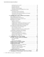 4
4 -
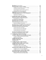 5
5 -
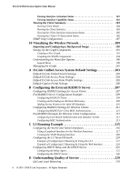 6
6 -
 7
7 -
8
-
9
-
10
-
11
-
12
-
13
-
14
-
15
-
16
-
17
-
18
-
19
-
20
-
21
-
22
-
23
-
24
-
25
-
26
-
27
-
28
-
29
-
30
-
31
-
32
-
33
-
34
-
35
-
36
-
37
-
38
-
39
-
40
-
41
-
42
-
43
-
44
-
45
-
46
-
47
-
48
-
49
-
50
-
51
-
52
-
53
-
54
-
55
-
56
-
57
-
58
-
59
-
60
-
61
-
62
-
63
-
64
-
65
-
66
-
67
-
68
-
69
-
70
-
71
-
72
-
73
-
74
-
75
-
76
-
77
-
78
-
79
-
80
-
81
-
82
-
83
-
84
-
85
-
86
-
87
-
88
-
89
-
90
-
91
-
92
-
93
-
94
-
95
-
96
-
97
-
98
-
99
-
100
-
101
-
102
-
103
-
104
-
105
-
106
-
107
-
108
-
109
-
110
-
111
-
112
-
113
-
114
-
115
-
116
-
117
-
118
-
119
-
120
-
121
-
122
-
123
-
124
-
125
-
126
-
127
-
128
-
129
-
130
-
131
-
132
-
133
-
134
-
135
-
136
-
137
-
138
-
139
-
140
-
141
-
142
-
143
-
144
-
145
-
146
-
147
-
148
-
149
-
150
-
151
-
152
-
153
-
154
-
155
-
156
-
157
-
158
-
159
-
160
-
161
-
162
-
163
-
164
-
165
-
166
-
167
-
168
-
169
-
170
-
171
-
172
-
173
-
174
-
175
-
176
-
177
-
178
-
179
-
180
-
181
-
182
-
183
-
184
-
185
-
186
-
187
-
188
-
189
-
190
-
191
-
192
-
193
-
194
-
195
-
196
-
197
-
198
-
199
-
200
-
201
-
202
-
203
-
204
-
205
-
206
-
207
-
208
-
209
-
210
-
211
-
212
-
213
-
214
-
215
-
216
-
217
-
218
-
219
-
220
-
221
-
222
-
223
-
224
-
225
-
226
-
227
-
228
-
229
-
230
-
231
-
232
-
233
-
234
-
235
-
236
-
237
-
238
-
239
-
240
-
241
-
242
-
243
-
244
-
245
-
246
-
247
-
248
-
249
-
250
-
251
-
252
-
253
-
254
-
255
-
256
-
257
-
258
-
259
-
260
-
261
-
262
-
263
-
264
-
265
-
266
-
267
-
268
-
269
-
270
 |
 |
