Dell Inspiron 15 AMD Service Manual - Page 26
Display Bezel
 |
View all Dell Inspiron 15 AMD manuals
Add to My Manuals
Save this manual to your list of manuals |
Page 26 highlights
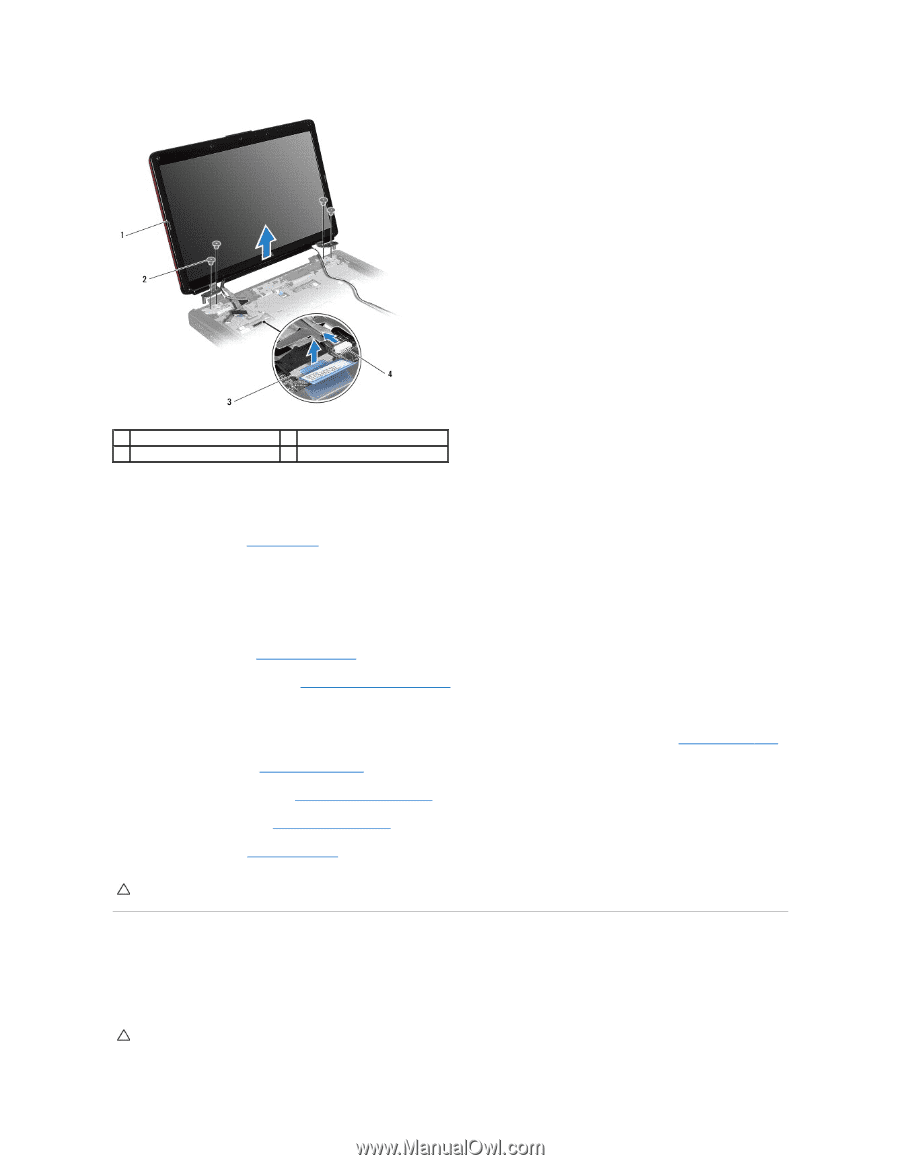
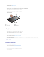
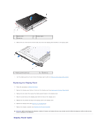
1 display assembly 3 display cable connector 2 screws (4) 4 camera cable connector Replacing the Display Assembly 1. Follow the procedures in Before You Begin. 2. Place the display assembly in position and replace the four screws that secure the display assembly to the computer base. 3. Route the display cable and camera cable into their routing guides and connect the cables to the respective system board connectors. 4. Route the Mini-Card antenna cables, and guide the cables to the bottom of the computer through the cable routing slot. 5. Replace the keyboard (see Replacing the Keyboard). 6. Replace the center control cover (see Replacing the Center Control Cover). 7. Replace the two screws at the bottom of the computer. 8. Route the Mini-Card antenna cables through the routing guides at the bottom of the computer, and replace the Mini-Card (see Replacing the Mini-Card). 9. Replace the hard drive (see Replacing the Hard Drive). 10. Replace the memory module(s) (see Replacing the Memory Module(s)). 11. Replace the module cover (see Replacing the Module Cover). 12. Replace the battery (see Replacing the Battery). CAUTION: Before turning on the computer, replace all screws and ensure that no stray screws remain inside the computer. Failure to do so may result in damage to the computer. Display Bezel Removing the Display Bezel CAUTION: The display bezel is extremely fragile. Be careful when removing it to prevent damaging the bezel.
-
 1
1 -
2
-
3
-
4
-
5
-
6
-
7
-
8
-
9
-
10
-
11
-
12
-
13
-
14
-
15
-
16
-
17
-
18
-
19
-
20
-
 21
21 -
 22
22 -
 23
23 -
 24
24 -
 25
25 -
 26
26 -
 27
27 -
 28
28 -
 29
29 -
 30
30 -
 31
31 -
32
-
33
-
34
-
35
-
36
-
37
-
38
-
39
-
40
-
41
-
42
-
43
-
44
-
45
-
46
-
47
-
48
-
49
-
50
-
51
-
52
-
53
-
54
 |
 |