Dell Inspiron 27 7710 All-in-One Service Manual - Page 62
The screws that secure the middle frame and display panel to the display-assembly base are silver in color
 |
View all Dell Inspiron 27 7710 All-in-One manuals
Add to My Manuals
Save this manual to your list of manuals |
Page 62 highlights
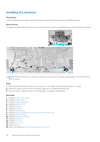
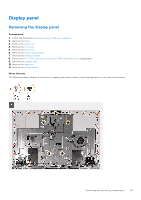
Steps 1. Align and place the display panel on the slots of the display-assembly base. 2. Route the display backlight, touchscreen and display cable through the slots on the display assembly base. 3. Place the display-assembly base on a clean and flat surface with the display panel facing down. 4. Replace the 12 screws (M3x5) that secure the display panel to the display-assembly base. 5. Replace the five screws (M3x5) that secure the display panel to the display-assembly base. NOTE: The screws that secure the middle frame and display panel to the display-assembly base are silver in color and etched with "LCD" around the screw holes. Next steps 1. Install the system board. 2. Install the heat sink. 3. Install the wireless card. 4. Install the M.2 2230 solid-state drive or M.2 2280 solid-state drive. 5. Install the memory module. 6. Install the system-board shield. 7. Install the hard drive. 8. Install the I/O cover. 9. Install the back cover. 10. Install the stand. 11. Follow the procedure in After working inside your computer. 62 Removing and installing components
-
 1
1 -
2
-
3
-
4
-
5
-
6
-
7
-
8
-
9
-
10
-
11
-
12
-
13
-
14
-
15
-
16
-
17
-
18
-
19
-
20
-
21
-
22
-
23
-
24
-
25
-
26
-
27
-
28
-
29
-
30
-
31
-
32
-
33
-
34
-
35
-
36
-
37
-
38
-
39
-
40
-
41
-
42
-
43
-
44
-
45
-
46
-
47
-
48
-
49
-
50
-
51
-
52
-
53
-
54
-
55
-
56
-
 57
57 -
 58
58 -
 59
59 -
 60
60 -
 61
61 -
 62
62 -
 63
63 -
 64
64 -
 65
65 -
 66
66 -
 67
67 -
68
-
69
-
70
-
71
-
72
-
73
-
74
-
75
-
76
-
77
-
78
-
79
-
80
-
81
-
82
-
83
-
84
-
85
 |
 |
